
Vertical centrifugal machine and damping base thereof

A vertical centrifuge and centrifuge technology, applied in the direction of centrifuges, springs/shock absorbers, mechanical equipment, etc., can solve the problem of poor shock absorption effect of the vertical centrifuge shock-absorbing base and affect the service life of the vertical centrifuge and reliability, noise and other issues, to improve convenience and efficiency, improve shock absorption effect, and optimize the operating environment

Inactive Publication Date: 2021-11-12
江苏汉光智能科技有限公司
View PDF9 Cites 0 Cited by
  • Summary
  • Abstract
  • Description
  • Claims
  • Application Information

AI Technical Summary

Problems solved by technology

[0005] Aiming at the deficiencies of the prior art, the present invention provides a vertical centrifuge and its shock-absorbing base, which have the ability to reduce noise, optimize the operating environment of the staff, improve the comfort of the staff operating the vertical centrifuge, and It can improve the convenience and efficiency of cleaning the separation net cylinder inside the vertical centrifuge, and can effectively improve the shock absorption effect of the vertical centrifuge shock-absorbing base through air shock absorption, and at the same time make the shock-absorbing base have the ability of shock-absorbing adjustment , so that it can buffer different degrees of vibration, and can avoid the hard vibration generated when the vertical centrifuge starts working to damage its internal electronic equipment, thereby improving the service life and reliability of the vertical centrifuge, and solving the problem of vertical centrifuges in There is a lot of noise during use, and at the same time, it solves the problem that the shock absorption effect of the vertical centrifuge base is poor, and affects the service life and reliability of the vertical centrifuge.

Method used


Image

  • Vertical centrifugal machine and damping base thereof
  • Vertical centrifugal machine and damping base thereof
  • Vertical centrifugal machine and damping base thereof

Examples


Embodiment Construction

[0026] The technical solutions in the embodiments of the present invention will be clearly and completely described below. Obviously, the described embodiments are only some of the embodiments of the present invention, but not all of them. Based on the embodiments of the present invention, all other embodiments obtained by persons of ordinary skill in the art without creative efforts fall within the protection scope of the present invention.

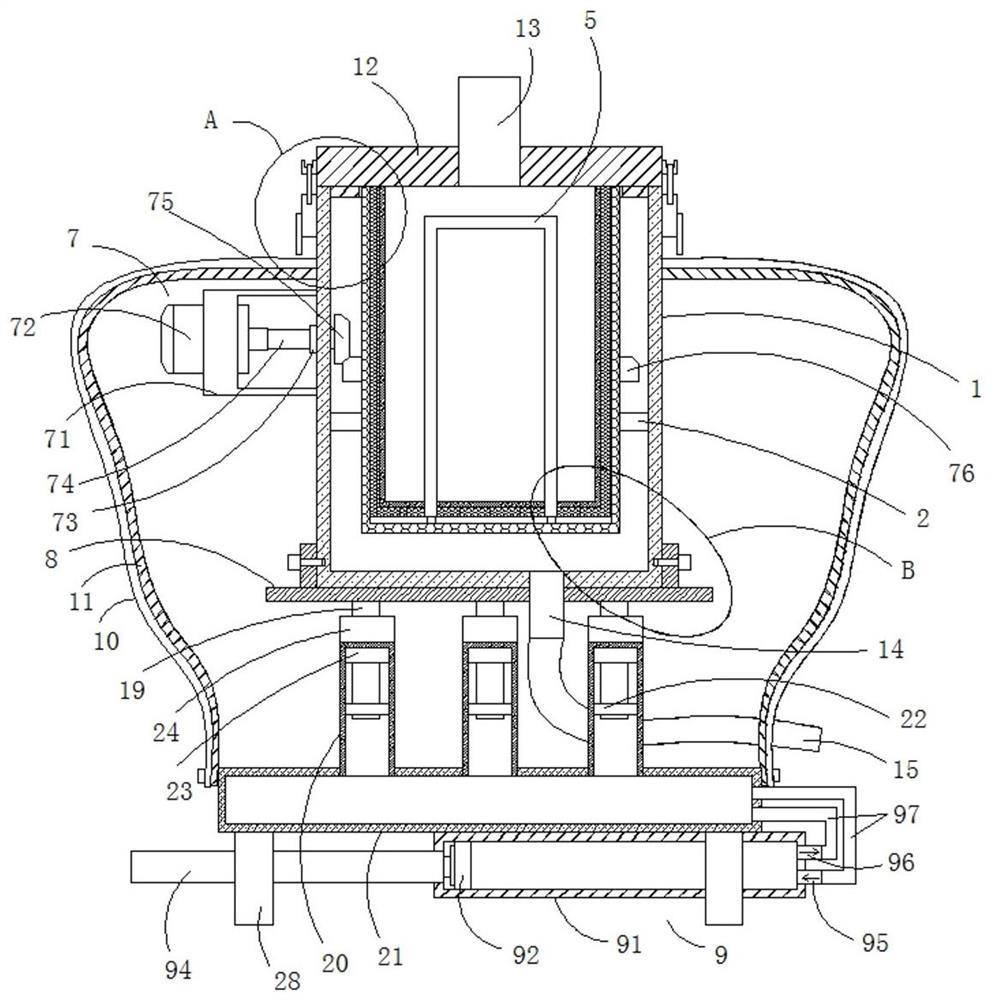
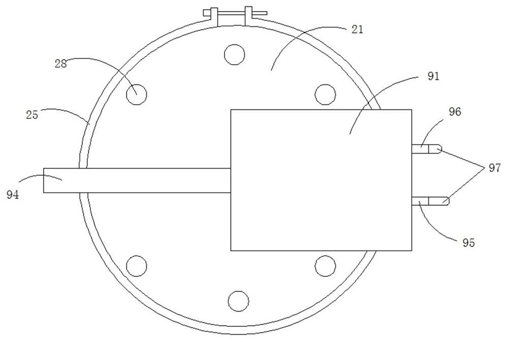
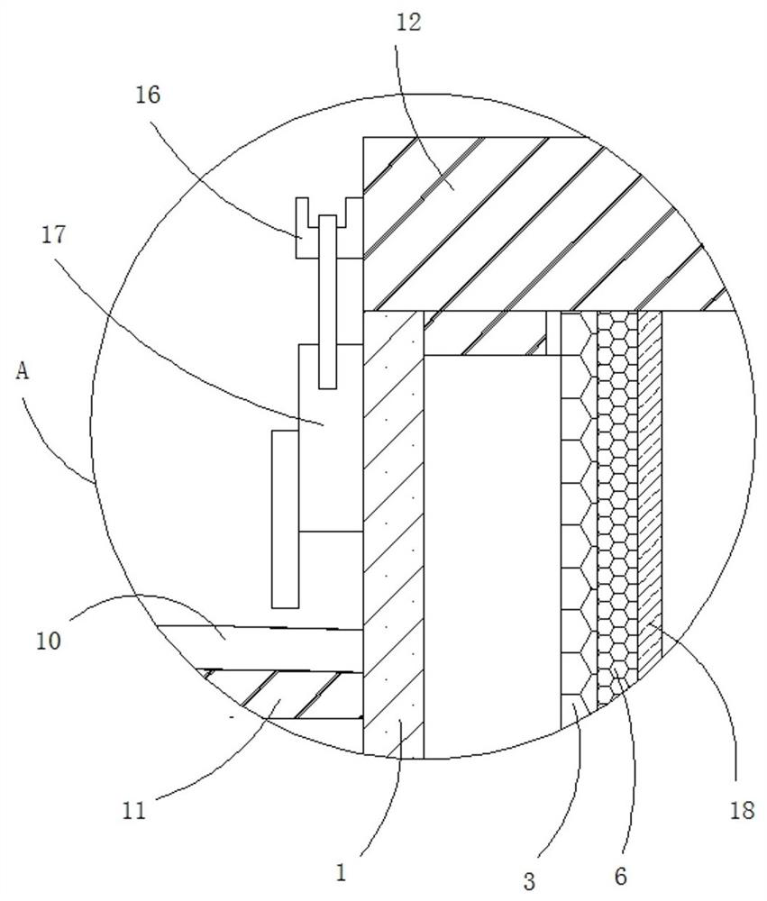
[0027] see Figure 1-Figure 5 , a vertical centrifuge, comprising a housing 1, the bottom inner wall of the housing 1 is fixedly connected with a rolling bearing 2, the inner wall of the rolling bearing 2 is fixedly connected with a support net cylinder 3, and the inner wall of the support net cylinder 3 is fixedly connected with two connecting Rod 4, the rod walls of the two connecting rods 4 are jointly sleeved with a U-shaped sleeve 5, the outer wall of the U-shaped sleeve 5 is fixedly sleeved with a separation net cylinder 6, the out...


PUM


Abstract

The invention relates to the technical field of centrifugal separation equipment, and discloses a vertical centrifugal machine and a damping base thereof; the vertical centrifugal machine comprises a shell; a rolling bearing is fixedly connected to the inner wall of the bottom end of the shell; a supporting net cylinder is fixedly connected to the inner wall of the rolling bearing; and two connecting rods are fixedly connected to the inner wall of the supporting net cylinder. According to the vertical centrifugal machine and the damping base thereof, the noise reduction capacity is achieved; the operating environment of workers is optimized; the comfort of operating the vertical centrifugal machine by the workers is improved; the convenience and efficiency of cleaning a separation net barrel in the vertical centrifugal machine can be improved; the damping effect of the damping base of the vertical centrifugal machine can be effectively improved through air damping; meanwhile, the damping base has the damping adjusting capacity; vibration of different degrees can be buffered; it can be avoided that hard vibration generated when the vertical centrifugal machine is started to work damages electronic equipment in the vertical centrifugal machine; and the service life and the reliability of the vertical centrifugal machine are improved.

Description

technical field [0001] The invention relates to the technical field of centrifugal separation equipment, in particular to a vertical centrifuge and a shock-absorbing base thereof. Background technique [0002] The vertical centrifuge is often used in the solid-liquid separation process of the slurry. The whole system of the vertical centrifuge cleverly uses the dual effects of centrifugal force and gravity to realize the continuous operation of the equipment and achieve high working efficiency. The slurry is produced by The feed inlet enters the centrifuge, and is subjected to centrifugal force in the separation system. The solid is retained through the filter screen, and the liquid passes through the screen into the filter chamber and is discharged from the liquid outlet. The solid moves downward under the component force of gravity and centrifugal force, and enters the lower section through the discharge bin. [0003] Existing vertical centrifuges are noisy when in use, w...

Claims


Application Information

Patent Timeline
Patent Type & Authority Applications(China)
IPC IPC(8): B04B7/00F16F15/023F16F15/06
CPCB04B7/00F16F15/0232F16F15/06
Inventor 王志
Owner 江苏汉光智能科技有限公司
Learn More