Power distribution box for power transmission line modular design

A technology of modular design and transmission lines, applied in substation/distribution device housing, electrical components, substation/switch layout details, etc., can solve the problems of reducing the working efficiency of power distribution cabinets and increasing the ambient heat of other power distribution devices, etc. Achieve the effects of improving heat dissipation, increasing size, and accelerating flow efficiency

Inactive Publication Date: 2021-11-09
翁瑞
View PDF0 Cites 0 Cited by
  • Summary
  • Abstract
  • Description
  • Claims
  • Application Information

AI Technical Summary

Problems solved by technology

[0006] Aiming at the deficiencies of the prior art, the present invention provides a power distribution box for the modular design of transmission lines, which solves the problem that when the heat released in one place in the traditional power distribution cabinet increases, it will be conducted to the surroundings of other power distribution devices through the air, increasing the The ambient heat of other power distribution devices reduces the overall working efficiency of the power distribution cabinet

Method used


Image

  • Power distribution box for power transmission line modular design
  • Power distribution box for power transmission line modular design
  • Power distribution box for power transmission line modular design

Examples


Embodiment Construction

[0029] The following will clearly and completely describe the technical solutions in the embodiments of the present invention with reference to the accompanying drawings in the embodiments of the present invention. Obviously, the described embodiments are only some, not all, embodiments of the present invention. Based on the embodiments of the present invention, all other embodiments obtained by persons of ordinary skill in the art without making creative efforts belong to the protection scope of the present invention.

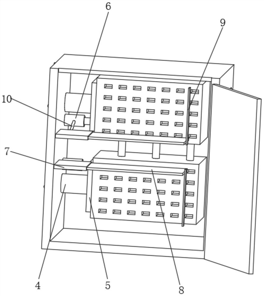
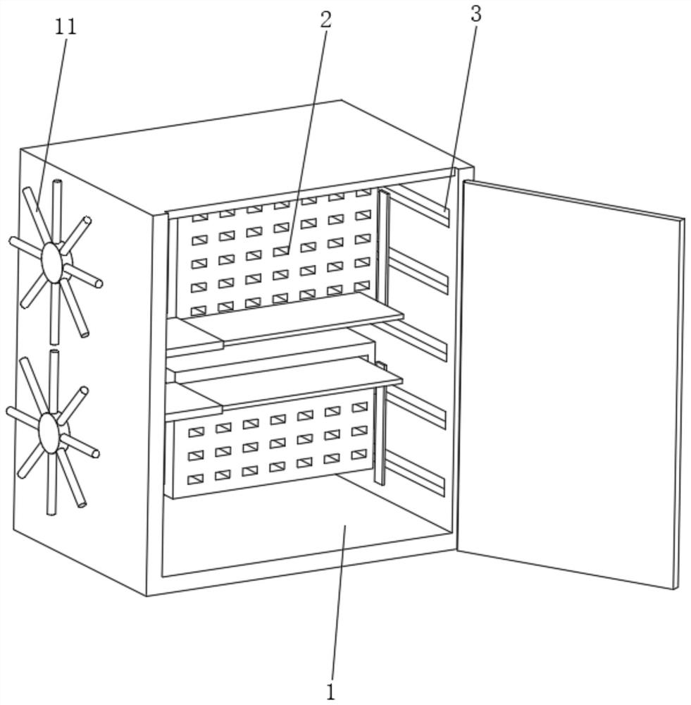
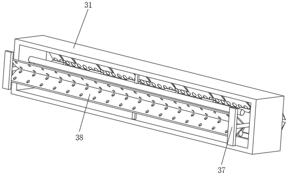
[0030] like Figure 1-6 As shown, the present invention provides a technical solution: a power distribution box for modular design of transmission lines, including a power distribution cabinet 1. The vertical position on the right side of the interior is evenly equipped with a ventilation adjustment mechanism 3, and the upper and lower ends of the left side of the power distribution cabinet 1 are penetrated and slidably connected with a heat conduction rod 4, ...


PUM


Abstract

The invention discloses a power distribution box for power transmission line modular design. The power distribution box comprises a power distribution cabinet body, power distribution devices are uniformly arranged in the power distribution cabinet body, and ventilation adjusting mechanisms are uniformly arranged at the vertical position of the right side in the power distribution cabinet body; heat conduction rods penetrate through the upper and lower ends of the left side in the power distribution cabinet body and are slidably connected with the upper and lower ends of the left side in the power distribution cabinet body, a contact adjusting mechanism is fixedly connected to the end, located in the power distribution cabinet body, of each heat conduction rod, and an air rod is fixedly connected to the left side in the power distribution cabinet body and located at the side, close to the middle, of the heat conduction rod; a corrugated blocking piece is movably connected into the right side of a storage supporting plate, a contact pressing piece is fixedly connected to the vertical position of the right end of the corrugated blocking piece, and the end, located outside the power distribution cabinet body, of the heat conduction rod is uniformly and fixedly connected with the distributed heat dissipation rods. The invention relates to the technical field of power transmission lines, and according to the power distribution box for the power transmission line modular design, the air environment of the power distribution devices at the upper and lower positions is blocked, the heat conducted to the air pressure part is reduced, and the overall working efficiency of the power distribution cabinet is guaranteed.

Description

technical field [0001] The invention relates to the technical field of power transmission lines, in particular to a power distribution box for modular design of power transmission lines. Background technique [0002] The transmission line is realized by using a transformer to boost the electric energy generated by the generator, and then connecting it to the transmission line through control equipment such as a circuit breaker. Structural forms, transmission lines are divided into overhead transmission lines and cable lines. [0003] The overhead transmission line is composed of line towers, wires, insulators, line fittings, guy wires, tower foundations, grounding devices, etc., and is erected above the ground. According to the nature of the transmission current, power transmission is divided into AC transmission and DC transmission. [0004] When the heat released from one part of the traditional power distribution cabinet increases, it will be conducted to the surroundin...

Claims


Application Information

Patent Timeline
IPC IPC(8): H02B1/56H02B1/28H02B1/04H02B1/46H02B1/48
CPCH02B1/565H02B1/28H02B1/04H02B1/46H02B1/48
Inventor 翁瑞
Owner 翁瑞
Why Eureka
Try Eureka