
An energy-saving transformer with high stability wall-mounted components

An energy-saving transformer and transformer technology, applied in the field of transformers, can solve problems such as troublesome installation, poor heat dissipation, and unfavorable operation

Active Publication Date: 2021-12-07
江苏鼎豪电力工程有限公司
View PDF4 Cites 0 Cited by
  • Summary
  • Abstract
  • Description
  • Claims
  • Application Information

AI Technical Summary

Problems solved by technology

[0004] The purpose of the present invention is: in order to solve the problem that the existing energy-saving transformer needs to use multiple bolts to install the transformer on the wall, and the transformer needs to be lifted during the installation process. It is more troublesome and not conducive to operation. At the same time, because the existing transformer avoids being far away from the wall, the heat dissipation effect will be poor, and the heat will not be easily dissipated during use. However, ordinary heat dissipation methods cannot achieve a good heat dissipation effect, resulting in the transformer being used for a long time. In the process of use, internal failures are prone to occur, and an energy-saving transformer with high-stability wall-mounted components is proposed

Method used


Image

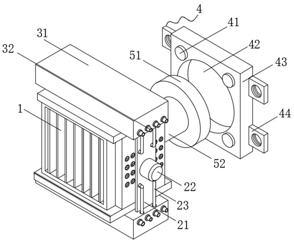
  • An energy-saving transformer with high stability wall-mounted components
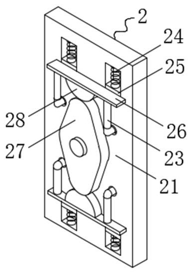
  • An energy-saving transformer with high stability wall-mounted components
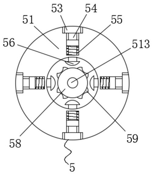
  • An energy-saving transformer with high stability wall-mounted components

Examples


Embodiment Construction

[0041] Next, the technical solutions in the embodiments of the present invention will be described in connection with the drawings of the embodiments of the present invention, and it is understood that the described embodiments are merely the embodiments of the present invention, not all of the embodiments. Based on the embodiments in the present invention, those of ordinary skill in the art will belong to the scope of the present invention without all other embodiments obtained in the preparation of creative labor.

[0042] See Figure 1-8 The present invention provides a technical solution: an energy-saving transformer with a high stable wall mount assembly, including a transformer body 1, and both the upper and lower sides of the transformer body 1 are provided with a heat sink body 3, and the upper left side surface of the transformer body 1 is all. The drive mechanism 2 is provided, and the upper and lower ends of the drive mechanism 2 are fixed to the opposite surface of the ...


PUM


Abstract

The invention discloses an energy-saving transformer with a high-stability wall-mounted component, which belongs to the technical field of transformers and includes a transformer body. The upper and lower sides of the transformer body are provided with heat dissipation mechanisms, and the left and right sides of the transformer body are provided with driving mechanisms. , the upper and lower ends of the driving mechanism are respectively fixedly connected to the opposite surfaces of the two heat dissipation mechanisms. In the present invention, by setting the heat dissipation mechanism, when the pressure plate moves close to the transformer body, it can squeeze the air bag, and the air in the air bag can be sprayed out through a plurality of nozzles, and the nozzles blow cold air into the inside of the transformer body. The side airbags can spray air at the same time. At this time, the air blown into the transformer body can form convection, absorb heat and squeeze each other. Finally, the hot air is evenly sprayed out through the multiple heat dissipation holes on the left and right sides of the transformer body to achieve the best cooling effect on the transformer body. The effect of internal heat dissipation.

Description

Technical field [0001] The present invention belongs to the technical field of the transformer, in particular, it relates to one kind of energy-saving transformers with a high stable wall assembly. Background technique [0002] Refers to the principle of a transformer using electromagnetic induction to change an AC voltage, the main member is a primary coil, secondary coil and the core. The main function of the transformer are: voltage conversion current conversion, impedance conversion, an isolated, regulated (magnetic saturation of the transformer) and the like, can be divided according to purpose: power transformers and special transformers. [0003] Current transformer energy needed during a plurality of bolts mounted on a wall mounted transformer, the transformer needs to be lifted during the installation, due to the large weight of the transformer, and thus are more cumbersome installation process is not conducive to the operation, and is currently By avoiding transformer a...

Claims


Application Information

Patent Timeline
Patent Type & Authority Patents(China)
IPC IPC(8): H01F27/20H01F27/08H01F27/06H01F27/02H01F27/23
CPCH01F27/20H01F27/06H01F27/08H01F27/23H01F27/025
Inventor 王楠
Owner 江苏鼎豪电力工程有限公司
Learn More