
Contra-rotating paddle ocean current energy power generation device applying magnetic coupling

A magnetic coupling and power generation device technology, which is applied in hydroelectric power generation, machine/engine, reaction engine, etc., can solve problems such as inability to adapt to complex sea conditions, complex coupling structure, low energy conversion efficiency, etc., and achieve good start-up performance, compactness and low space requirements

Active Publication Date: 2021-11-09
ZHEJIANG UNIV
View PDF11 Cites 0 Cited by
  • Summary
  • Abstract
  • Description
  • Claims
  • Application Information

AI Technical Summary

Problems solved by technology

[0005] Aiming at the problems that the existing ocean current power generation device cannot adapt to complex sea conditions, low energy conversion efficiency, large sealing loss, and complex coupling structure and difficult sealing during torque transmission, the present invention proposes a permanent magnet, through magnetic force A counter-rotating propeller sea current power generation device that realizes counter-rotating power transmission by means of coupling transmission

Method used


Image

  • Contra-rotating paddle ocean current energy power generation device applying magnetic coupling
  • Contra-rotating paddle ocean current energy power generation device applying magnetic coupling
  • Contra-rotating paddle ocean current energy power generation device applying magnetic coupling

Examples


Embodiment Construction

[0032] According to the following drawings and preferred embodiments of the present invention will be described in detail, the purpose and effect of the present invention will become more apparent, it should be understood that the specific embodiments described herein are merely used to explain the present invention and are not intended to limit the present invention. Based on the embodiments in the present invention, all other embodiments obtained without making creative labor without making creative labor.

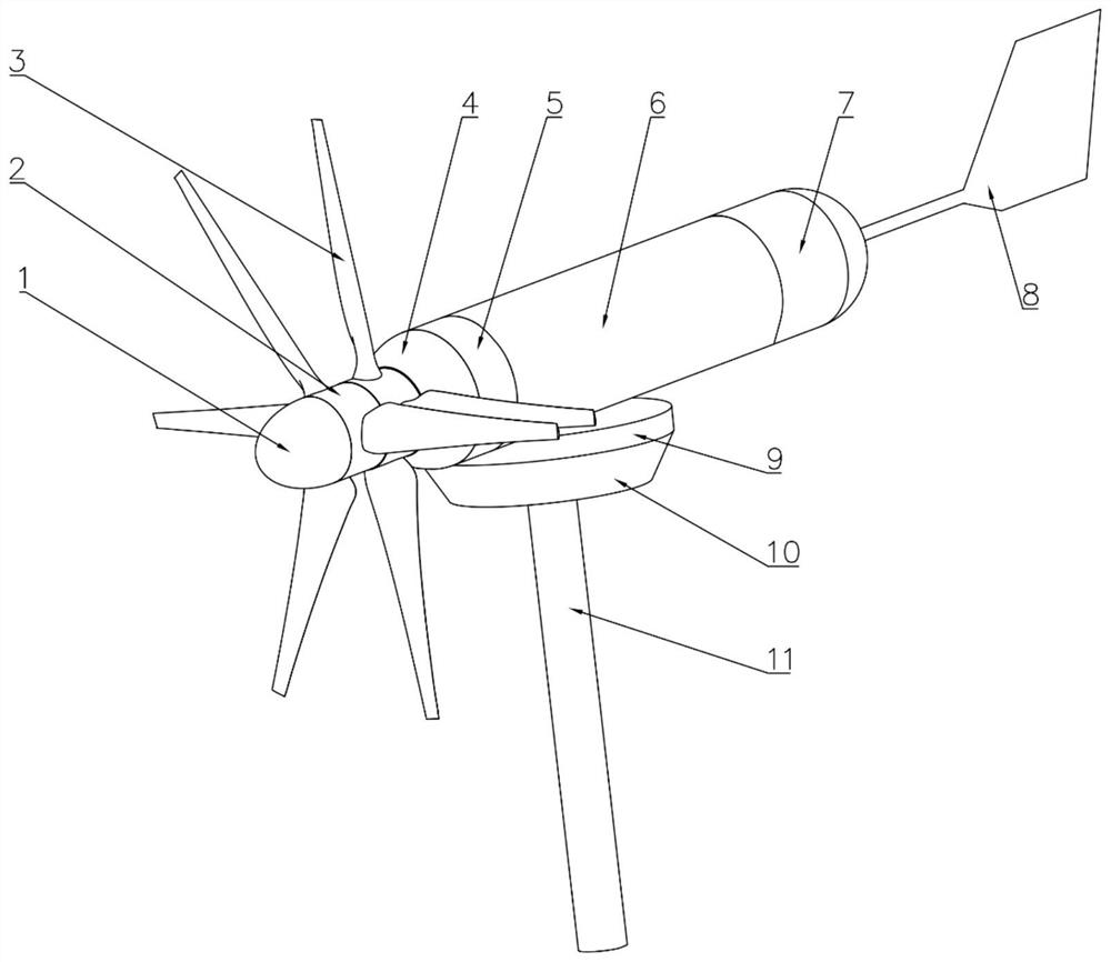
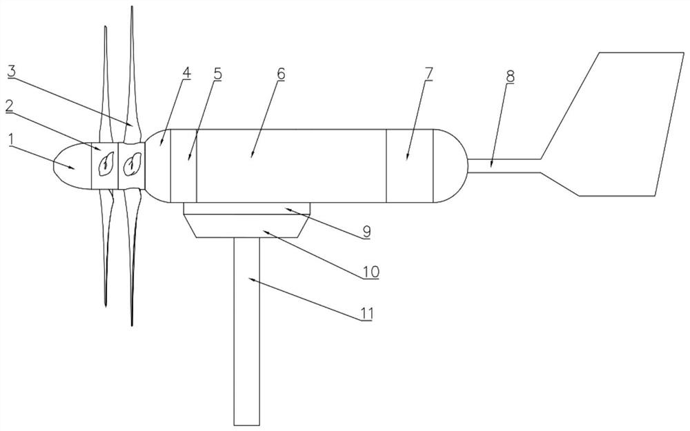
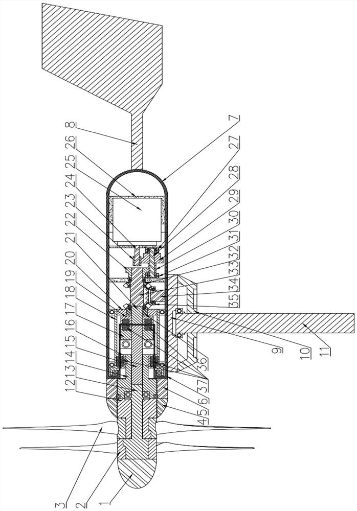
[0033] like Figure 1 ~ 3 As shown in, for Kaplan ocean current power generation apparatus applied magnetic coupling embodiment of the present invention comprises a housing, located outside the housing for rotation of the impeller, and yaw steering means located inside the housing and magnetic coupling means, mechanical transmission means and the generator means.

[0034]The housing includes a guide housing 4, a rear housing 5, a central housing 6, and a rear housing 7, which...


PUM


Abstract

The invention discloses a contra-rotating paddle ocean current energy power generation device applying a magnetic coupling. The contra-rotating paddle ocean current energy power generation device comprises a shell, a contra-rotating impeller, a steering and yawing device, a magnetic coupling device, a mechanical speed change device and a power generator device. The contra-rotating impeller is installed at the front end of the power generation device, blades rotate around a center shaft under the impact of incoming flow and generate tangential force for driving a rotating shaft to rotate, and the two sets of blades transmit torque to the input end of the magnetic coupling through an inner shaft and an outer shaft respectively. The magnetic coupling transmits the torque of a contra-rotating shaft from the outside of the power generation device to the inside of the power generation device in a non-contact manner by using the combination of an axial coupling and a radial coupling in a push-and-pull coupling transmission manner of permanent magnets in heteropole arrangement. The mechanical speed change device conducts torque coupling on contra-rotating torque, single-shaft output is achieved, and speed change is conducted through a gear mechanism. An inner rotor of a generator is connected with the mechanical speed change device and rotates along with the mechanical speed change device to achieve the cutting magnetic induction line motion with an outer stator for power generation. The device is compact in structure and high in kinetic energy conversion rate.

Description

Technical field [0001] The present invention is in the field of ocean current power generation, particularly relates to an application of the magnetic coupling Kaplan ocean current power generation apparatus. Background technique [0002] Energy is a key factor in development of human society, and non-renewable fossil fuel energy to achieve sustainable development of human society, in today's world have set his sights on the development and use of renewable energy, ocean current energy is one of them. Current energy utilized is seawater directional flow the kinetic energy, highly predictable, energy density, and clean renewable waves by impact of small features. Meanwhile, my country's current energy reserves are abundant, development and utilization of its enormous potential. If the flow of energy into the sea Seafloor Observatory Network in power, while meeting its electricity needs with low flow rate and high reliability, good start performance and efficient conversion of kine...

Claims


Application Information

Patent Timeline
Patent Type & Authority Applications(China)
IPC IPC(8): F03B3/14F03B11/00F03B11/02F03B11/06F03B13/00
CPCF03B3/145F03B11/00F03B11/02F03B11/06F03B11/006F03B13/00Y02E10/20
Inventor 黄滨王超龚寅晨王鹏忠赵博文
Owner ZHEJIANG UNIV
Learn More