Eureka AIR delivers breakthrough ideas for toughest innovation challenges, trusted by R&D personnel around the world.

Vehicle body rear part force transmission structure

A technology for the rear of the body and the body, which is applied to the superstructure, superstructure sub-assemblies, vehicle components, etc., can solve the problem of poor rigidity in the installation area of ​​the rear shock absorber, safety threats to the occupants in the vehicle, interruption of the force transmission channel and other problems. Misconnection and other problems, to achieve the effect of improving collision performance, improving force transmission performance, and improving rigidity performance

Active Publication Date: 2021-11-09
GREAT WALL MOTOR CO LTD
View PDF4 Cites 0 Cited by
  • Summary
  • Abstract
  • Description
  • Claims
  • Application Information

AI Technical Summary

Problems solved by technology

[0003] In the current car body rear structure, for the excitation of the rear shock absorber installation area, due to the interruption and misconnection of the force transmission channel in the rear body force transmission structure to which this area belongs, and the rigidity of the rear shock absorber installation area Insufficient
When the vehicle collides, the interruption or misconnection of the power transmission channel at the rear of the vehicle body is prone to bending, which will also pose a threat to the safety of the occupants in the vehicle
In addition, when the vehicle is running, when the installation structure of the rear shock absorber is affected by external excitation, the area with weak rigidity will easily transmit noise and vibration to the interior of the cab, which will bring discomfort to the driving of the vehicle.

Method used


Image

  • Vehicle body rear part force transmission structure
  • Vehicle body rear part force transmission structure
  • Vehicle body rear part force transmission structure

Examples


Embodiment Construction

[0034] It should be noted that, in the case of no conflict, the embodiments of the present invention and the features in the embodiments can be combined with each other.

[0035] The present invention will be described in detail below with reference to the accompanying drawings and examples.

[0036] This embodiment relates to a force transmission structure at the rear of the vehicle body, wherein the vehicle body in this embodiment is specifically the body of a car model, and the force transmission structure at the rear of the vehicle body in this embodiment is specifically used to form the body that is excited by the body. The conduction in the rear part is expected to improve the transmission of the excitation to the rear part of the vehicle body, thereby improving the crash performance, and at the same time improving the stiffness performance of the rear part of the vehicle body.

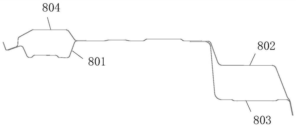
[0037] For specific settings, such as figure 1 As shown, in the rear force transmission str...


PUM


Abstract

The invention provides a vehicle body rear part force transmission structure which is used for forming transmission of excitation of a vehicle body in the rear part of the vehicle body, and the vehicle body rear part force transmission structure comprises a rear floor cross beam, a shelf, and a first force transmission ring structure which is formed by two rear floor longitudinal beams, a rear shock absorber reinforcing plate and a C column. According to the vehicle body rear portion force transmission structure, through the first force transmission ring structure formed by the rear floor cross beam, the shelf, the rear floor longitudinal beams on the two sides, the rear shock absorber reinforcing plate and the C columns, the force transmission performance of a rear shock absorber installation area on the rear portion of the vehicle body can be improved, and the safety risk of a driver and passengers in the vehicle can be reduced.

Description

technical field [0001] The invention relates to the technical field of car body structures, in particular to a force transmission structure at the rear of a car body. Background technique [0002] In vehicles, taking a car as an example, the rear structure of the body plays a vital role in the force transmission and NVH performance of the vehicle body. A high-performance rear structure can significantly improve the driving comfort of the vehicle, and can also improve the driving safety factor. [0003] In the current car body rear structure, for the excitation of the rear shock absorber installation area, due to the interruption and misconnection of the force transmission channel in the rear body force transmission structure to which this area belongs, and the rigidity of the rear shock absorber installation area Not enough. When the vehicle collides, the interruption or misconnection of the power transmission channel at the rear of the vehicle body is prone to bending, wh...

Claims


Application Information

Patent Timeline
IPC IPC(8): B62D25/08B62D25/20
CPCB62D25/08B62D25/20
Inventor 麻瑞祥刘绍辉宫瑞伟何桂军刘杰吴昊卢广亮张印权王建彬王延鹏崔爱云张书任
Owner GREAT WALL MOTOR CO LTD
Why Eureka
Eureka Blog
Learn More