Damping pressure lock

A pressure lock and joint technology, applied in casters, wheels, transportation and packaging, etc., to achieve reasonable design, good braking effect and cushioning effect, and good stability in use

Pending Publication Date: 2021-11-09
NORTHWEST A & F UNIV
View PDF0 Cites 0 Cited by
  • Summary
  • Abstract
  • Description
  • Claims
  • Application Information

AI Technical Summary

Problems solved by technology

However, few existing products can easily and conveniently undertake these functions.

Method used


Image

  • Damping pressure lock
  • Damping pressure lock
  • Damping pressure lock

Examples


Embodiment Construction

[0020] The technical scheme of this patent will be described in further detail below in conjunction with specific embodiments

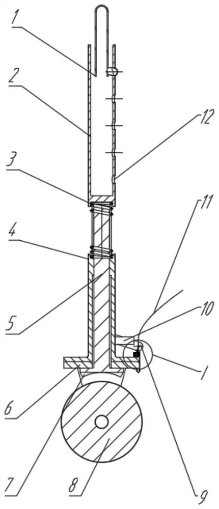
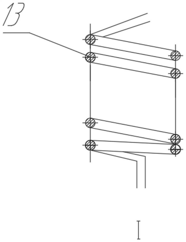
[0021] A shock-absorbing pressure lock, including a folding shrapnel (1), a connecting pipe (2), a connecting spring (3), a base (4), a brake lever (5), a wheel seat (6), a brake pad (7), and a wheel (8), pull plate (9), seat plate (10), brake cable (11), fixing hole (12), locking spring (13) and handle part.

[0022] A shock-absorbing pressure lock, including a folding shrapnel (1), a connecting pipe (2), a connecting spring (3), a base (4), a brake lever (5), a wheel seat (6), a brake pad (7), and a wheel (8), pull plate (9), seat plate (10), brake cable (11), fixing hole (12), locking spring (13) and handle part.

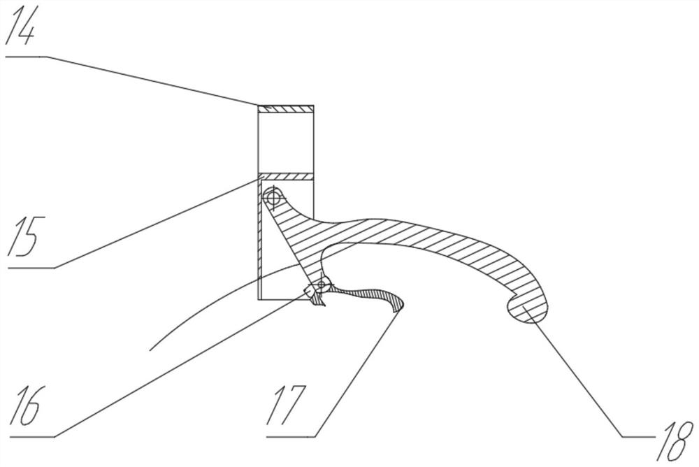
[0023] The handle part includes: a fixed cover (14), a fixed frame (15), a locking hole (16), a locking handle (17), and a pulling handle (18).

[0024] The connecting pipe (2) is connected to other mechanical connecting pipes through ...


PUM


Abstract

The invention discloses a damping pressure lock which is characterized in that a connecting spring is arranged between a connecting pipe and a base, a brake rod is sleeved with the base, the connecting pipe can descend along with the brake rod when being stressed, and at the moment, a brake pad on the brake rod can make contact with a wheel to achieve braking; a handle part on the device is connected with a brake cable, the brake cable drives a brake rod to ascend and descend after the handle is pulled, and the functions of manual braking and brake releasing are achieved. Meanwhile, the connecting spring between the connecting pipe and the base enables the device to have a cushioning function; the device achieves the functions of self-locking, cushioning and manual braking at the same time.

Description

technical field [0001] This patent relates to a shock-absorbing pressure lock, specifically a lock that controls the braking of a brake pad through a handle. Background technique [0002] The brake cushioning device is used on walking aids and other sports devices. On the one hand, the walking aid needs a braking function that can be realized by the hand. On the other hand, in order to improve comfort and ensure safety when the user is walking, a The cushioning function, and it needs to be able to lock itself when the walker is under pressure to prevent accidents. And existing products can bear these functions simply and conveniently less. Contents of the invention [0003] Aiming at the above contents, the present invention provides a shock-absorbing pressure lock with simple structure, easy adjustment, flexible operation and reliable braking. [0004] In order to achieve the above object, this patent provides the following technical solutions. [0005] A shock-absorbi...

Claims


Application Information

Patent Timeline
Patent Type & Authority Applications(China)
IPC IPC(8): B60B33/00B60B33/04
CPCB60B33/0081B60B33/045
Inventor 胡耀华钟定军胡星王一帆杨沛佶禅久毅
Owner NORTHWEST A & F UNIV
Why Eureka
Try Eureka