
Vertical cutter installing machine

A tool-mounting and vertical technology, which is applied in metal processing, metal processing equipment, manufacturing tools, etc., can solve the problems of small number of workpieces, low efficiency of tool installation, and low efficiency of use, so as to reduce equipment costs, improve installation efficiency, The effect of shaft reduction

Pending Publication Date: 2021-11-09
HUNAN ZDCY (ZHONGDA CHUANG YUAN) CNC EQUIP CO LTD
View PDF0 Cites 1 Cited by
  • Summary
  • Abstract
  • Description
  • Claims
  • Application Information

AI Technical Summary

Problems solved by technology

[0002] In the prior art, the horizontal adjustment method used for the correction of the spiral bevel gear cutting tool is limited by its own principle, and there is a problem of low tool loading efficiency
At the same time, this method detects the flank of the cutting edge of the strip blade and adjusts it accordingly. In practical applications, based on the wear of the grinding wheel of the knife grinder, the change of the flank is relatively large, and the part involved in cutting is the cutting edge. , there is a certain adjustment error in the measurement of the flank, which leads to a small number of processed workpieces and low efficiency

Method used


Image

  • Vertical cutter installing machine
  • Vertical cutter installing machine
  • Vertical cutter installing machine

Examples


Embodiment Construction

[0029] In order to enable those skilled in the art to better understand the technical solutions of the present invention, the present invention will be further described in detail below in conjunction with the accompanying drawings and specific embodiments.

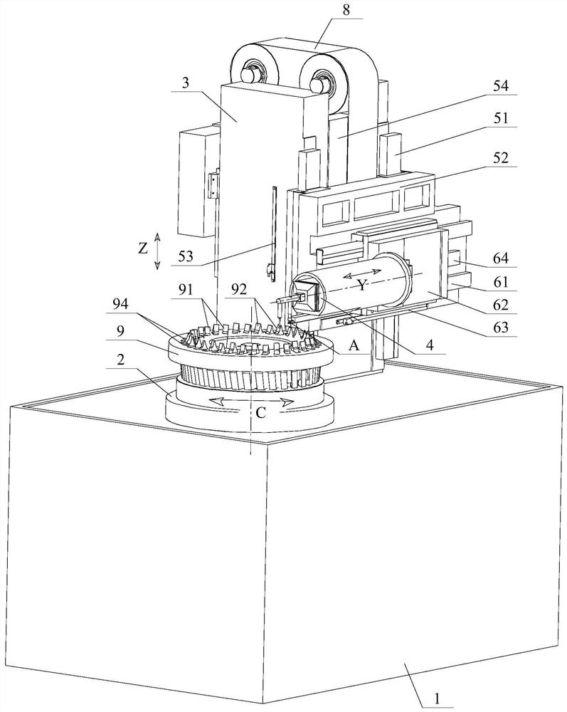
[0030] See figure 1 , which is a schematic diagram of the overall structure of the vertical knife loading machine described in this embodiment.

[0031] The vertical tool loading machine is used to correct the cutting tool of the spiral bevel gear. As shown in the figure, the bed 1 is used as the basic structure of the machine tool, and the workpiece spindle 2 and the column 3 are arranged on it. The workpiece spindle 2 can rotate in the direction shown by the arrow C to form a single installation shaft system, and its axis of rotation is parallel to the Z axis; the cutter head 9 of the tool to be tested can be installed on the workpiece spindle 2, and can The main shaft 2 also rotates around its axis of rotation. In th...


PUM


Abstract

The invention discloses a vertical cutter installing machine, which is used for correcting a cutting tool of a spiral bevel gear and comprises a stand column and a workpiece main shaft which are arranged on a machine body and further comprises a three-dimensional measuring head which moves along the Y axis and the Z axis relative to the stand column through a sliding assembly, and a rotating shaft of the workpiece main shaft is parallel to the Z axis; a measuring rod of the three-dimensional measuring head extends out of a body of the three-dimensional measuring head, a height measuring needle and a radial measuring needle are arranged on the measuring rod, the height measuring needle is used for detecting the height position of a tool nose of a cutting tool to be detected, and the radial measuring needle is used for detecting the radial position of a blade of the cutting tool to be detected; and a tool pressing device is fixedly arranged on the body of the three-dimensional measuring head and provided with a tool pressing part, and the tool pressing part can abut against the tool nose of the cutting tool to be detected in a pressing mode along the Z axis. According to the scheme, the adjustment precision can be effectively improved through structural optimization, and the operation efficiency is improved.

Description

technical field [0001] The invention relates to the technical field of mechanical processing, in particular to a vertical tool loading machine for correcting spiral bevel gear cutting tools. Background technique [0002] In the prior art, the horizontal adjustment method for correcting the cutting tool of the spiral bevel gear is limited by its own principle, and there is a problem of low tool loading efficiency. At the same time, this method detects the flank of the cutting edge of the strip blade and adjusts it accordingly. In practical applications, based on the wear of the grinding wheel of the knife grinder, the change of the flank is relatively large, and the part involved in cutting is the cutting edge. , There is a certain adjustment error in the measurement of the flank, which leads to a small number of processed workpieces and low efficiency. [0003] In view of this, it is urgent to optimize the design of the calibration equipment for spiral bevel gear cutting to...

Claims


Application Information

Patent Timeline
Patent Type & Authority Applications(China)
IPC IPC(8): B23P19/00B23P19/10
CPCB23P19/00B23P19/10
Inventor 李国胜邹文毅杨超肖超群
Owner HUNAN ZDCY (ZHONGDA CHUANG YUAN) CNC EQUIP CO LTD
Learn More