
Foldable massage bed

A massage bed and bed leg technology, which is applied in the field of massage beds, can solve the problems of easy loosening and damage of folding massage beds, and achieve the effects of convenient installation and use, not easy to deform, and reduced transportation costs.

Pending Publication Date: 2021-11-09
北京孤岛科技有限公司
View PDF7 Cites 0 Cited by
  • Summary
  • Abstract
  • Description
  • Claims
  • Application Information

AI Technical Summary

Problems solved by technology

[0003] The purpose of the present invention is to solve the technical problem that the existing folding massage bed is easy to be loose and damaged after long-term use, and to provide a foldable massage bed

Method used


Image

  • Foldable massage bed
  • Foldable massage bed
  • Foldable massage bed

Examples


Embodiment 1

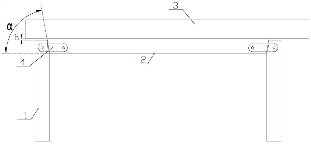
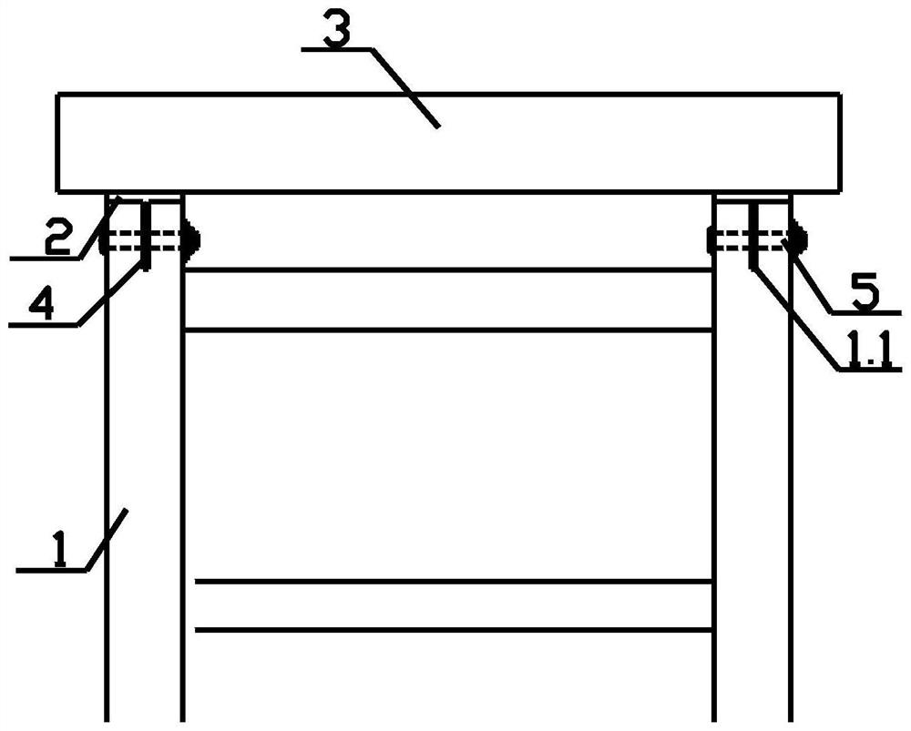
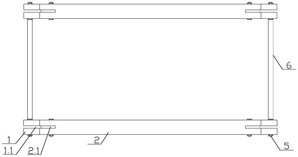
[0039] Such as Figure 1-5 As shown, a foldable massage bed includes four bed legs 1, two beams 2 and several connecting rods 6, the upper parts of the four bed legs 1 are arranged at the two ends of the two beams 2, the Several connecting rods 6 are arranged between two beams 2 and two bed legs 1 on the same side;

[0040] It also includes four connecting pieces 4 and eight bolts 5. The upper side of the bed leg 1 connected to the beam 2 is an inclined surface, and a first card slot 1.1 is vertically opened in the middle of the inclined surface. In the middle of the inclined surface of the bed leg 1 A shallow groove 1.2 is horizontally provided, and the two ends of the beam 2 are inclined surfaces compatible with the inclined surface of the bed leg 1, and a second card slot 2.1 is vertically set in the middle of the inclined surface of the beam 2, and the bed leg 1 and the cross beam The angle between the inclined surface of 2 and the horizontal plane is 80°, the inclined su...

Embodiment 2

[0044] Such as Figure 6-13 As shown, compared with Embodiment 1, the present embodiment is fixed with a first fastener 7 by screws 9 on the inclined surface of the bed leg 1, and is fixed with a second fastener on the inclined surface of the beam 2 by screws 9. 8. Other structures are the same as those in Example 1;

[0045] The middle of the first fastener main board 7.1 of the first fastener 7 is provided with a rectangular hole 7.4, the upper end is provided with an upper ear plate 7.6, and the middle of the first fastener main board 7.1 below the rectangular hole 7.4 is vertically provided with a first Fastener card slot 7.5, the two sides of the first fastener main board 7.1 are symmetrically provided with a first ear plate 7.2, and a first connecting hole 7.3 is opened on the first ear plate 7.2, and the first fastener main board 7.1 and The two first ear plates 7.2 are arranged in a U shape, and several screw holes are provided on the first fastener main board 7.1, th...


PUM


Abstract

The invention belongs to the technical field of massage beds, and particularly relates to a foldable massage bed. In order to solve the technical problem that an existing foldable massage bed is prone to loosening and damage after being used for a long time, the technical scheme is as follows: the foldable massage bed comprises four connecting pieces and eight bolts; one side face of the upper end of each of four bed legs is an inclined face; furthermore, a first clamping groove is vertically formed in the middle of each inclined face; the two end faces of two cross beams are inclined faces matched with the inclined faces of the bed legs; second clamping grooves are perpendicularly formed in the middles of the inclined faces of the cross beams; the inclined faces of the bed legs make contact with the inclined faces of the cross beams; the four connecting pieces are arranged in communicating grooves formed by the first clamping grooves and the second clamping grooves; the connecting pieces are connected with the bed legs through bolts in the first clamping grooves; and the connecting piece is connected with the cross beam through a bolt in the second clamping groove. When the foldable massage bed disclosed by the invention is used, the cross beam is deeply embedded between the inclined faces of the bed legs under the action of gravity and pushing force; the friction force of the contact surfaces of the bed legs and the cross beam is larger; and the longer the time is, the more stable the structure is.

Description

technical field [0001] The invention belongs to the technical field of massage beds, in particular to a foldable massage bed. Background technique [0002] Existing foldable massage beds usually use mortise and tenon structure or movable metal connectors to achieve the folding effect. Since the massage bed is repeatedly pushed by the masseur for a long time during use, it is easy to cause fatigue damage to the connectors or the mortise and tenon structure, making massage The bed structure is loose or even damaged. Contents of the invention [0003] The purpose of the present invention is to solve the technical problem that the existing folding massage bed is easy to be loose and damaged after being used for a long time, and to provide a foldable massage bed. [0004] In order to solve the problems of the technologies described above, the technical solution adopted in the present invention is: [0005] A foldable massage bed, including four bed legs, two beams and several...

Claims


Application Information

Patent Timeline
Patent Type & Authority Applications(China)
IPC IPC(8): A61G13/00A61G13/10
CPCA61G13/009A61G13/10
Inventor 张泽民高俊龙
Owner 北京孤岛科技有限公司
Learn More