Image processing method and device
An image processing and target image technology, applied in the field of electronic information, can solve problems such as poor image quality
- Summary
- Abstract
- Description
- Claims
- Application Information
AI Technical Summary
Problems solved by technology
Method used
Image
Examples
example 1
[0108] Example 1: When it is only necessary to increase the number of preset receiver devices:
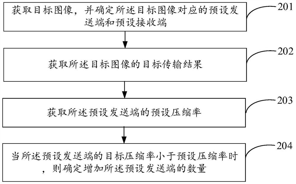
[0109] When the resolution of the target image is 8K, if the image resolution supported by the sending end is 8K, and the image resolution supported by the receiving end is 2K, then according to the resolution of the target image, it is necessary to match 4 receiving ends to meet the conditions The encoding and decoding requirements of the image avoid the degradation of image quality after encoding and decoding processing.
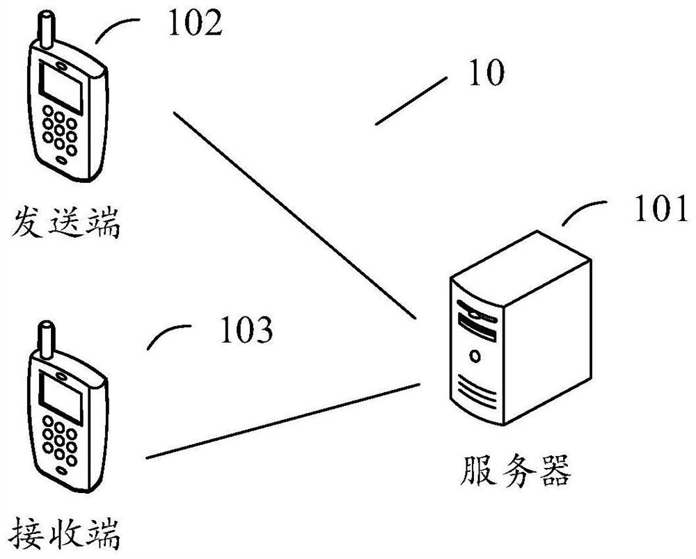
[0110] like Figure 2a The structure of the image processing system shown in includes: one sender corresponds to multiple receivers, and the data is split when the sender encodes, and the split data is sent to each receiver respectively, and finally the fusion device is fused for display .
example 2
[0111] Example 2: When it is necessary to increase the number of preset sender and preset receiver devices at the same time:
[0112] When the resolution of the target image is 8K, if the image resolution supported by the sender is 2K, and the image resolution supported by the receiver is 2K, then according to the resolution of the target image, it is necessary to match 4 preset sender and The four receiving ends can meet the encoding and decoding requirements of the image, so as to avoid the degradation of the image quality after the encoding and decoding processing.
[0113] like Figure 2bThe structure of the image processing system shown includes: multiple sending ends correspond to multiple receiving ends, then the data is split after the source end collects, and the split data is sent to each sending end, and each sending end sends to the corresponding at the receiving end, and finally displayed by the fusion device after fusion.
example 3
[0114] Example 3: When it is necessary to only increase the number of preset senders:
[0115] When the resolution of the target image is 8K, if the image resolution supported by the sending end is 2K, and the image resolution supported by the receiving end is 8K, then according to the resolution of the target image, it is necessary to match 4 preset Satisfy the encoding and decoding requirements of the image, and avoid the degradation of image quality after encoding and decoding.
[0116] like Figure 2c The structure of the image processing system shown includes: multiple senders correspond to a receiver, then the data is split after the source is collected, and the split data is sent to each sender, and each sender is sent to the receiver end, and finally the receiving end performs data fusion and displays it.
[0117] In the image processing method provided by the embodiments of the present disclosure, after the target image is acquired, the target image is transmitted t...
PUM
 Abstract
Description
Claims
Application Information
 - R&D
- Intellectual Property
- Life Sciences
- Materials
- Tech Scout
- Unparalleled Data Quality
- Higher Quality Content
- 60% Fewer Hallucinations
Browse by: Latest US Patents, China's latest patents, Technical Efficacy Thesaurus, Application Domain, Technology Topic, Popular Technical Reports.
© 2025 PatSnap. All rights reserved.Legal|Privacy policy|Modern Slavery Act Transparency Statement|Sitemap|About US| Contact US: help@patsnap.com


