New energy building wall

A technology for building walls and new energy, applied in construction, building components, sustainable buildings, etc., can solve the problems of energy consumption, inconvenient disassembly and assembly, inability to adjust the angle, etc., to achieve energy saving, simple and practical structure, and accident prevention. drop effect

Active Publication Date: 2021-11-05
北京化典科技有限公司
View PDF7 Cites 0 Cited by
  • Summary
  • Abstract
  • Description
  • Claims
  • Application Information

AI Technical Summary

Problems solved by technology

Although this kind of means of using cooling and heating terminal equipment to achieve indoor temperature adjustment is effective, it is all at the cost of energy consumption, high usage costs, and environmental pollution.
[0003] At present, some existing technologies provide systems that do not consume traditional energy and can realize indoor temperature regulation, but the temperature regulation effect of the existing technologies is not obvious
In addition, in order to further utilize new energy, there are related technologies for mounting solar panels on the exterior walls of buildings in the prior art, but the existing solar panel mounting devices are not stable in installation, inconvenient in disassembly and assembly, and cannot be adjusted. angle

Method used


Image

  • New energy building wall
  • New energy building wall
  • New energy building wall

Examples


Embodiment Construction

[0043] In order to make the purpose, technical solutions and advantages of the embodiments of the present invention clearer, the technical solutions in the embodiments of the present invention will be clearly and completely described below in conjunction with the drawings in the embodiments of the present invention. Obviously, the described embodiments It is a part of embodiments of the present invention, but not all embodiments. The components of the embodiments of the invention generally described and illustrated in the figures herein may be arranged and designed in a variety of different configurations.

[0044] Accordingly, the following detailed description of the embodiments of the invention provided in the accompanying drawings is not intended to limit the scope of the claimed invention, but merely represents selected embodiments of the invention. Based on the embodiments of the present invention, all other embodiments obtained by persons of ordinary skill in the art wi...


PUM


Abstract

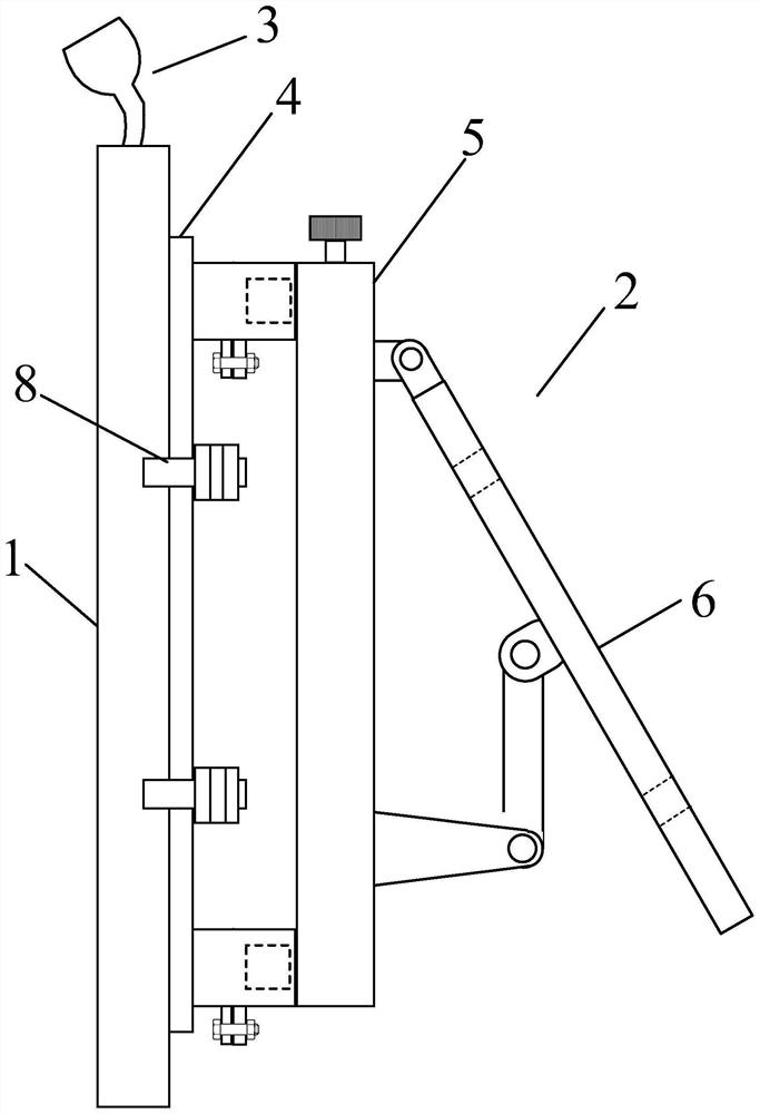
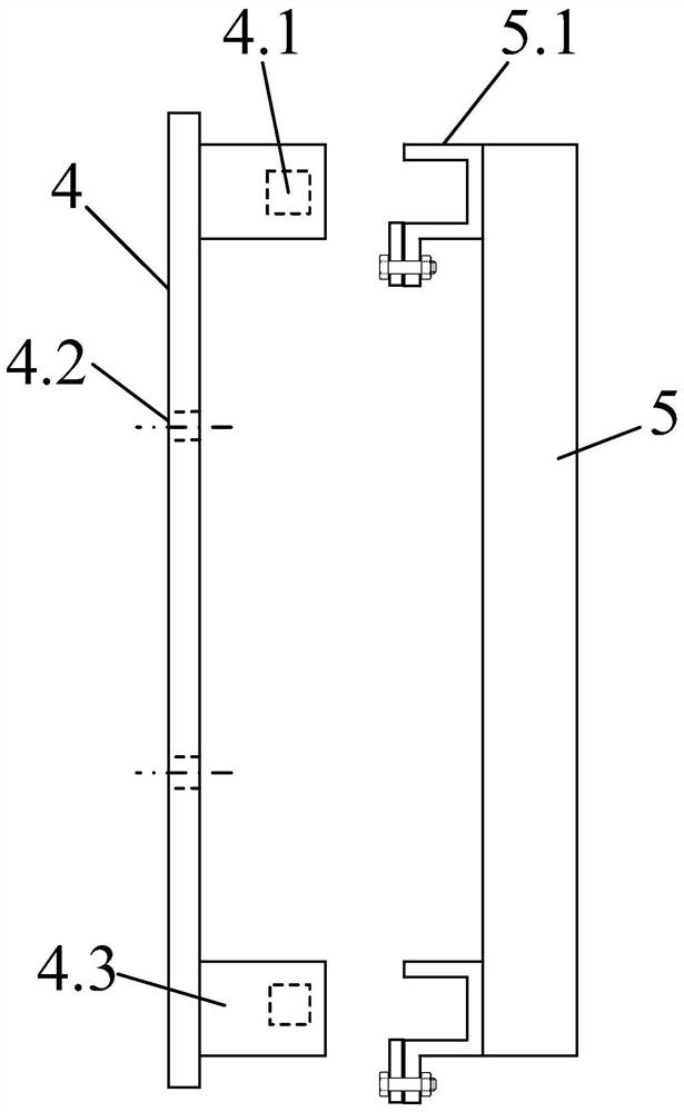
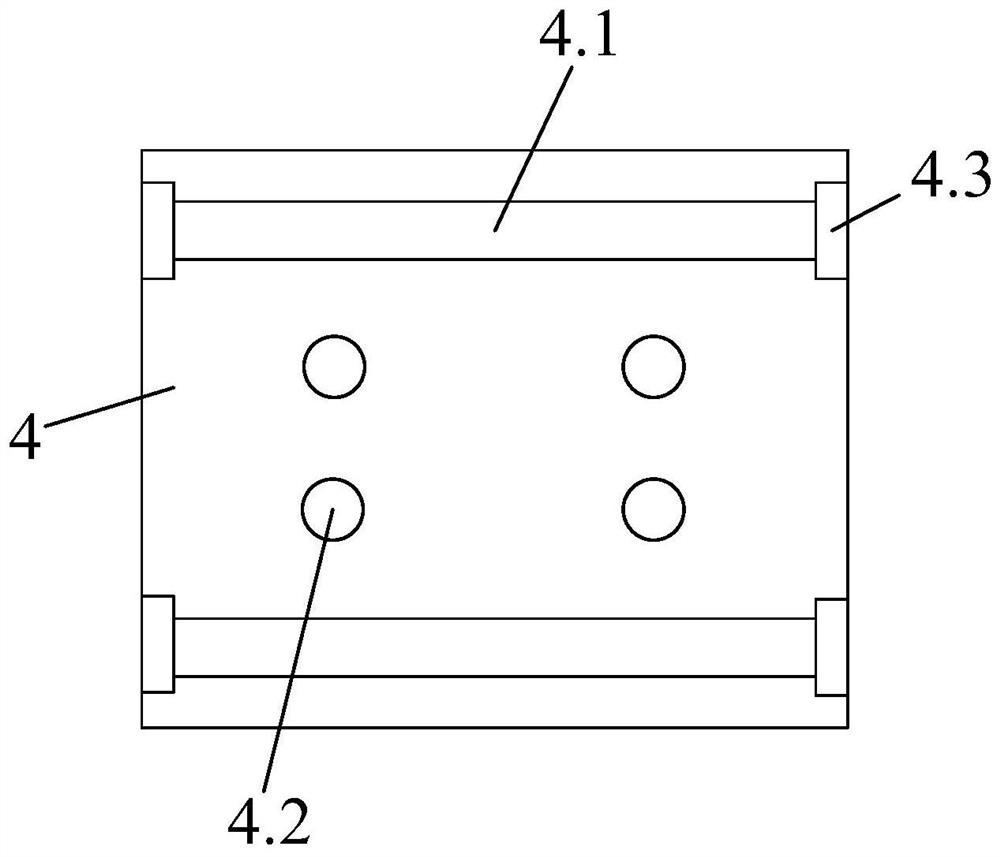
The invention discloses a new energy building wall. The new energy building wall comprises a wall body, a solar cell panel mounting frame mounted on the outer side of the wall body, and a solar light-gathering automatic temperature-regulating radiation mechanism mounted in the wall body; the solar cell panel mounting frame comprises a wall mounting plate, two solar cell panel supports and a cell panel mounting frame which is rotatably mounted on the solar cell panel supports; the upper end and the lower end of the wall mounting plate are respectively provided with a transverse mounting column with a square cross section, the upper end and the lower end of the back face of each solar cell panel support are respectively provided with a U-shaped hanging piece matched with a upper transverse mounting column and a lower transverse mounting column, and a upper U-shaped hanging piece and a lower U-shaped hanging piece are respectively hung on the upper transverse mounting column and the lower transverse mounting column and can perform positioning sliding in the left-right direction along the transverse mounting columns. According to the new energy building wall, through the arrangement of the transverse mounting columns and the U-shaped hanging pieces, the distance between the two solar cell panel supports can be adjusted, so that solar cell panels of different sizes can be mounted on the solar cell panel mounting frame.

Description

technical field [0001] The invention relates to the field of building walls, in particular to a new energy building wall. Background technique [0002] Traditional indoor temperature adjustment mostly uses electric air conditioners or heaters, etc., through the cooling and heating functions of air conditioners to make cold or hot air into the room, or through municipal heating to increase the indoor temperature, so as to achieve the purpose of cooling and heating to make the indoor temperature livable. Although this kind of means of using cooling and heating terminal equipment to achieve indoor temperature adjustment has a significant effect, it all comes at the cost of energy consumption, high usage costs, and at the same time causes environmental pollution. [0003] At present, some existing technologies provide a system that does not consume traditional energy and can realize indoor temperature regulation, but the temperature regulation effect of the prior art is not obvi...

Claims


Application Information

Patent Timeline
Patent Type & Authority Applications(China)
IPC IPC(8): E04B2/00H02S20/22H02S20/30F24F5/00F24S10/10F24S23/71F24S30/425
CPCE04B2/00H02S20/30H02S20/22F24F5/0089F24F5/0046F24S30/425F24S23/71F24S10/10F24F2005/0067Y02E10/44Y02E10/47Y02E10/50Y02B10/10Y02A30/272Y02B10/20
Inventor 王佩李帅
Owner 北京化典科技有限公司
Why Eureka
Try Eureka