
Continuous flow micro-electrolytic tank system device

A system device and micro-electrolysis cell technology, applied in the field of electrochemistry, can solve problems such as slow electrolysis efficiency, and achieve the effect of stable treatment and optimal electrolysis effect.

Pending Publication Date: 2021-11-05
SHENZHEN E ZHENG TECH
View PDF7 Cites 0 Cited by
  • Summary
  • Abstract
  • Description
  • Claims
  • Application Information

AI Technical Summary

Problems solved by technology

[0002] Electrochemistry is currently a hot topic in chemical synthesis. Electrochemical reaction is also commonly referred to as electrolytic reaction. Usually, two or more electrode sheets / rods are inserted into the reaction bottle, and then a certain amount of material is added. Release products for reaction research (that is, gap type electrochemical reactor). This application is relatively simple for theoretical research in the laboratory, and it needs to be set up and easy to operate. However, in the laboratory, the electrolyte is usually electrolyzed in batches. After electrolysis, it needs Pour out the reaction solution, put it back into the electrolyte and electrolyze again. The electrolysis efficiency is slow. Secondly, the electrolysis reaction usually exothermic or endothermic, and it is usually necessary to keep the temperature of the electrolyte constant to achieve the best electrolysis effect.

Method used


Image

  • Continuous flow micro-electrolytic tank system device
  • Continuous flow micro-electrolytic tank system device
  • Continuous flow micro-electrolytic tank system device

Examples


Embodiment Construction

[0036] The following will clearly and completely describe the technical solutions in the embodiments of the present invention with reference to the accompanying drawings in the embodiments of the present invention. Obviously, the described embodiments are only part of the embodiments of the present invention, not all of them. Based on the embodiments of the present invention, all other embodiments obtained by persons of ordinary skill in the art without creative efforts fall within the protection scope of the present invention.

[0037] In the description of the present invention, it should be noted that, unless otherwise specified and limited, the terms "installed", "set with", "connected", etc. should be understood in a broad sense, such as "connected", which may be a fixed connection , can also be detachably connected, or integrally connected; can be mechanically connected, can also be electrically connected; can be directly connected, can also be indirectly connected throug...


PUM


Abstract

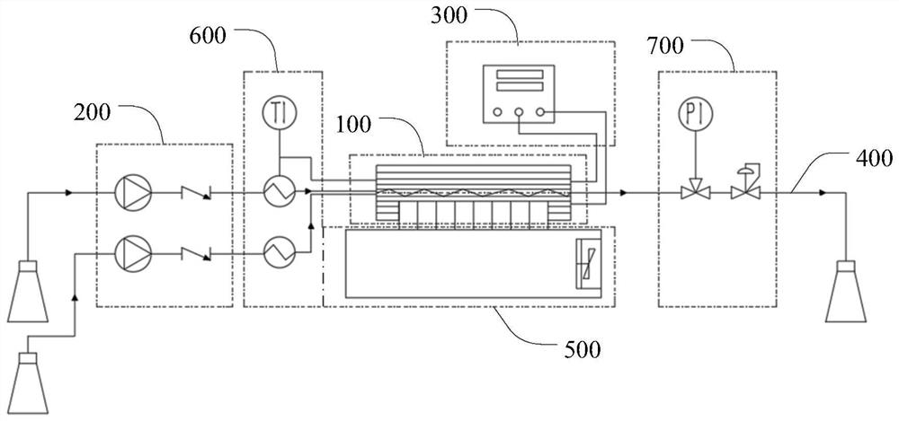
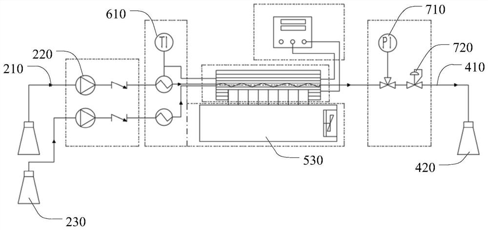
The invention discloses a continuous flow micro-electrolytic tank system device, which comprises: a reaction module, a feeding module, a power supply module, a material receiving module and a heat exchange module; the reaction module forms a reaction flow channel with a feeding hole and a discharging hole, and the reaction module discharges to perform electrochemical reaction on a material in the reaction flow channel to generate a reaction product; the feeding module is used for driving a material to flow through the reaction flow channel; the power supply module is electrically connected with the reaction module; the material receiving module is used for receiving a reaction product flowing out of the reaction flow channel; and the heat exchange module is connected with the reaction module and is used for exchanging cold energy or heat energy generated by the reaction module with the outside. According to the technical scheme, the material in a material tank is continuously fed into the reaction module through the feeding module, and the product after the reaction of the reaction module is continuously conveyed into a product tank, so that the reaction electrolyte can be stably treated, and the end-to-end production of the material and the product can be realized by combining with other continuous flow reaction or separation and purification steps.

Description

technical field [0001] The invention relates to the technical field of electrochemistry, in particular to a continuous-flow micro-electrolytic cell system device. Background technique [0002] Electrochemistry is currently a hot topic in chemical synthesis. Electrochemical reaction is also commonly referred to as electrolytic reaction. Usually, two or more electrode sheets / rods are inserted into the reaction bottle, and then a certain amount of material is added. Release products for reaction research (that is, gap type electrochemical reactor). This application is relatively simple for theoretical research in the laboratory, and it needs to be set up and easy to operate. However, in the laboratory, the electrolyte is usually electrolyzed in batches. After electrolysis, it needs Pour out the reaction solution, put it back into the electrolyte and electrolyze again. The electrolysis efficiency is slow. Secondly, the electrolysis reaction usually exotherms or absorbs heat, and...

Claims


Application Information

Patent Timeline
IPC IPC(8): C25B9/00C25B9/67C25B15/08C25B15/027C25B15/021C25C7/00C25C7/06F25B21/02
CPCC25B9/00C25B9/67C25B15/08C25B15/027C25B15/021C25C7/00C25C7/06F25B21/02Y02E60/50
Inventor 王春陈鸿文李嫣然张海彬王志磊卜春坡曾天宝钟明李正强
Owner SHENZHEN E ZHENG TECH
Learn More