Welding forming machine for bent pipe and flange connection

A flange welding and elbow connection technology, used in welding equipment, auxiliary welding equipment, welding/cutting auxiliary equipment, etc., can solve the problems of easy welding deviation, the need to adjust the angle of elbow and flange, and hidden dangers to workers. , to avoid potential safety hazards, improve welding efficiency and improve stability.

Active Publication Date: 2021-11-05
徐州市瑞泰钢管有限公司
View PDF10 Cites 6 Cited by
  • Summary
  • Abstract
  • Description
  • Claims
  • Application Information

AI Technical Summary

Problems solved by technology

[0003] However, there are currently the following problems in welding elbows and flanges: 1. In order to save costs, some small enterprises usually weld elbows and flanges manually. The pipe and the flange are fixed, and the existing fixture cannot adjust the angle between the elbow and the flange according to the welding requirements, which is prone to welding deviation and affects the welding effect
[0004] 2. Since the connection between the flange and the elbow needs to be welded in a circle, and when the workers weld the flange and the elbow, they need to rotate the flange and the elbow in turn, and the circumferential welding cannot be realized, so it affects the flange and the elbow. The welding efficiency of the elbow is high, and there are certain safety hazards when workers weld

Method used


Image

  • Welding forming machine for bent pipe and flange connection
  • Welding forming machine for bent pipe and flange connection
  • Welding forming machine for bent pipe and flange connection

Examples


Embodiment Construction

[0033]The embodiments of the present invention will be described in detail below with reference to the accompanying drawings, but the present invention can be implemented in many different ways defined and covered by the claims.

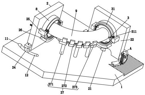
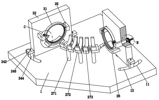
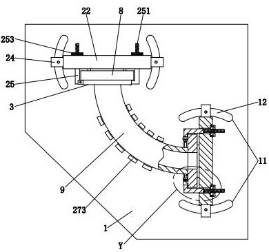
[0034] refer to figure 1 , figure 2 , image 3 , a flange welding and forming machine for elbow connection, comprising a bottom plate 1, a clamping unit 2 and a welding unit 3, two sliding groups 11 are arranged symmetrically on the upper end of the bottom plate 1, and the two sliding groups 11 are vertically arranged, And each sliding group 11 includes two oppositely arranged arc-shaped chutes 12, and the centers of circles of the two arc-shaped chutes 12 on each sliding group 11 coincide; 2 is provided with a welding unit 3 .

[0035] refer to figure 1 , figure 2 , Image 6 , Figure 7 , the clamping unit 2 includes a support column 21, a rotating plate 22, a sliding groove 23, a locking assembly 24, an L-shaped block 25, a baffle plate ...


PUM


Abstract

The invention relates to the technical field of pipeline welding, in particular to a welding forming machine for bent pipe and flange connection. The welding forming machine comprises a bottom plate, a clamping unit and a welding unit. The clamping unit is installed at the upper end of the bottom plate, and the welding unit is arranged on the clamping unit. The welding forming machine has the following problems that an existing clamp cannot adjust the angle between a bent pipe and flanges according to welding requirements, consequently, welding deviation is prone to being generated, circumferential welding cannot be realized when a worker welds the flanges and the bent pipe, the welding efficiency of the flanges and the bent pipe is influenced, and certain potential safety hazards exist when the worker carries out welding. By means of the welding forming machine, the angle between rotating plates and the bent pipe can be adjusted, the bent pipe and the flanges can be aligned conveniently, and therefore deviation generated when the bent pipe and the flanges are welded can be reduced; and by means of the welding forming machine, circumferential welding treatment can be carried out on the butt joint positions of the bent pipe and the flanges, the welding efficiency can be improved, and potential safety hazards existing during manual welding can be avoided.

Description

technical field [0001] The invention relates to the technical field of pipe welding, in particular to a welding and forming machine for connecting flanges of elbows. Background technique [0002] Pipes are parts used to transport gas, liquid or fluid with solid particles. Pipes are divided into straight pipes and curved pipes. The curved pipes are mainly used for the connection at the corners of the pipes. Generally, in order to facilitate the installation of the pipes, there will be Welded flanges at both ends such as Figure 9 shown, and it is convenient for the later disassembly and maintenance of the pipeline. [0003] However, there are currently the following problems in welding elbows and flanges: 1. In order to save costs, some small enterprises usually weld elbows and flanges manually. The pipe and the flange are fixed, and the existing fixture cannot adjust the angle between the elbow and the flange according to the welding requirements, which is prone to welding ...

Claims


Application Information

Patent Timeline
Patent Type & Authority Applications(China)
IPC IPC(8): B23K37/00B23K37/053B23K37/02
CPCB23K37/00B23K37/053B23K37/0211B23K37/0247B23K2101/06
Inventor 刘双勇
Owner 徐州市瑞泰钢管有限公司
Why Eureka
Try Eureka