Gas or liquid ultrasonic purification device

An ultrasonic and liquid technology, applied in the field of gas or liquid purification and purification equipment, can solve the problems of clogging, passivation, filtration and purification efficiency and quality, affecting the production efficiency of enterprises, etc. range, reduce the number of times of opening and flushing, and ensure the effect of filtration and purification efficiency

Pending Publication Date: 2021-11-05
唐腊辉
View PDF0 Cites 2 Cited by
  • Summary
  • Abstract
  • Description
  • Claims
  • Application Information

AI Technical Summary

Problems solved by technology

However, it is precisely because of the extremely small capillary pores on the wall of the fiber filter tube that the fiber filter tube has an extremely fine ultrafiltration function. Blockage, resulting in the simultaneous decline in filtration efficiency and quality
For this problem, there is no good solution at present, only by regularly opening the sewage port more frequently, and by consuming a certain amount of gas or liquid, the wall of the fiber filter tube can be washed or flushed.
In this way, to a certain extent, although the blockage of the tube wall can be alleviated and the service life of the fiber filter tube can be appropriately extended, the impurities embedded in the capillary pores cannot be completely washed off. It is also prone to clogging and passivation, leading to the loss of filtration performance; and this behavior of alleviating the clogging of the pipe wall has to be carried out by opening the sewage port frequently, which will cause a large amount of gas or liquid consumption, especially in some high-cost acquisition systems. Gas and liquid, which will greatly increase the daily operating costs of the enterprise, and often repeatedly wash the pipe wall, and easily affect the production efficiency of the enterprise

Method used


Image

  • Gas or liquid ultrasonic purification device
  • Gas or liquid ultrasonic purification device
  • Gas or liquid ultrasonic purification device

Examples


Embodiment Construction

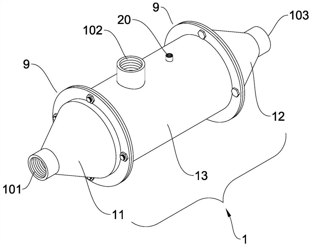
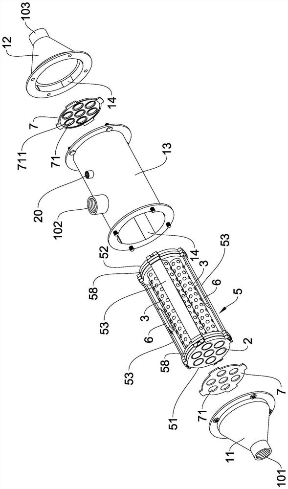
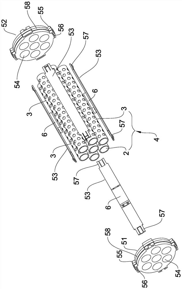
[0014] Such as figure 1 , figure 2 , Figure 5 As shown, a gas or liquid ultrasonic purification and purification device according to the present invention includes the following components: a housing 1, a number of fiber filter tubes 2, a number of hard mesh tubes 3, an internal support body 5, and an ultrasonic vibration element 6;

[0015] Wherein, the housing 1 is an outer shell with at least one end openable and having an input port 101 , a purification output port 102 and a sewage output port 103 . In order to make the shell 1 easy to process, and more convenient to maintain and clean, the preferred scheme of the shell 1 of the present invention is a structure that can be disassembled at both ends, specifically as Figure 5 As shown, the housing 1 includes a front cone cover 11, a rear cone cover 12 and a shell main body 13, and the shell main body 13 is arranged between the front cone cover 11 and the rear cone cover 12 and can be fixed with a flange structure 9. Ea...


PUM


Abstract

The invention relates to a gas or liquid ultrasonic purification device which comprises a shell, fiber filter pipes, a hard net pipe, an internal support body and an ultrasonic vibration element, the shell is a shell with an input port, a purification output port and a pollution discharge output port, and the fiber filter pipes are arranged in the hard net pipe in a sleeved mode to form a composite filter pipe assembly. The inner support body is provided with an installation space, the composite filter pipe assembly is sleeved and stacked in the installation space in a penetrating mode, the inner support body is sleeved with the shell, and the ultrasonic vibration element is installed on the inner support body. High-frequency ultrasonic vibration energy generated by the ultrasonic vibration element is applied to the internal support body, is fed back to the hard net pipe and then acts on the fiber filter pipes, so that the fiber filter pipes generate high-frequency ultrasonic resonance and internal molecular motion, impurities in gas or liquid do not block capillary pores of the fiber filter pipes and are prevented from being blocked and passivated, the service life is prolonged, the quality and efficiency of filtration and purification are ensured, and the replacement frequency and loss of the fiber filter pipes are reduced.

Description

technical field [0001] The invention relates to the field of gas or liquid purification and purification equipment, in particular to a purification and purification equipment with ultrasonic oscillation function. Background technique [0002] In the field of gas or liquid purification and purification, thin and thin fiber filter tubes are widely used in gas purification machines and central water purifiers because of their extremely fine ultrafiltration function. However, it is precisely because of the extremely small capillary pores on the wall of the fiber filter tube that the fiber filter tube has an extremely fine ultrafiltration function. Blockage, resulting in a simultaneous decline in filtration efficiency and quality. For this problem, there is still no good solution at present, and the sewage port can only be opened more frequently by timing, and by consuming a certain amount of gas or liquid, the wall of the fiber filter tube is washed or flushed. In this way, to...

Claims


Application Information

Patent Timeline
Patent Type & Authority Applications(China)
IPC IPC(8): B01D46/24B01D46/00B01D33/37B01D33/54
Inventor 唐腊辉
Owner 唐腊辉
Why Eureka
Try Eureka