
Reciprocating type high-pressure plunger pump for oilfield exploitation water treatment

A technology of high-pressure plunger pumps and exploiting water, which is applied in variable capacity pump parts, parts of pumping devices for elastic fluids, pumps, etc., and can solve inconvenient use, equipment damage, and inability to deal with shock absorption of equipment, etc. Problems, to achieve the effect of multiple functions, easy to disassemble or install

Active Publication Date: 2021-11-02
HUBEI PETROKH MACHINE MFG
View PDF5 Cites 0 Cited by
  • Summary
  • Abstract
  • Description
  • Claims
  • Application Information

AI Technical Summary

Problems solved by technology

[0002] In the process of oilfield exploitation, high-pressure plunger pump equipment is required to work and use. The operating pressure of high-pressure plunger pump should generally be between 10MPa and 100MPa. For the purpose of the liquid, the mechanical energy of the prime mover is directly converted into the pressure energy of the conveying liquid through the pump. The capacity of the pump only depends on the volume change value of the working chamber and the number of changes per unit time, and has nothing to do with the discharge pressure in theory. In the existing The pressure state of the high-pressure plunger pump is fixed and cannot be adjusted during use, so it cannot be used in different situations. In addition, the existing equipment cannot be damped during the use of the equipment, and long-term vibration will cause damage to the equipment itself. In addition, the existing equipment cannot be quickly disassembled when not in use, making it inconvenient to move. When the equipment is adjusted for shock absorption, the internal pressure can be adjusted at the same time to meet the needs of different situations. It is inconvenient to use

Method used


Image

  • Reciprocating type high-pressure plunger pump for oilfield exploitation water treatment
  • Reciprocating type high-pressure plunger pump for oilfield exploitation water treatment
  • Reciprocating type high-pressure plunger pump for oilfield exploitation water treatment

Examples


Embodiment approach

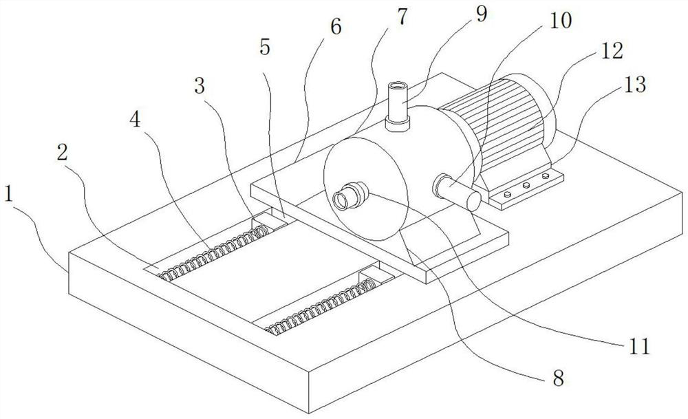
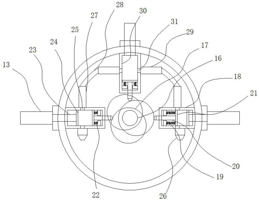
[0029] As a preferred embodiment of the present invention, a movable plate 24 is installed inside the pressurized chamber 18, a movable rod 23 is mounted on the movable plate 24, and one end of the movable rod 23 is mounted on the electric push rod 10 , A sealing ring is installed between the movable plate 24 and the inner wall of the pressurized chamber 18 .

[0030] As a preferred embodiment of the present invention, the top of the pressurized chamber 18 is provided with a water outlet 25, and a pipe 27 is installed on the water outlet 25, and a connecting pipe 28 is installed on the pipe 27. One end of connecting pipe 28 is fixed with pipeline two 29.

[0031] As a preferred embodiment of the present invention, a drain cavity 30 is installed at the bottom of the outlet pipe 9, and the drain cavity 30 is fixed on the inner wall of the working part 7, and a piston and a movable piston are installed inside the drain cavity 30. Column one, the drainage chamber 30 is provided w...


PUM


Abstract

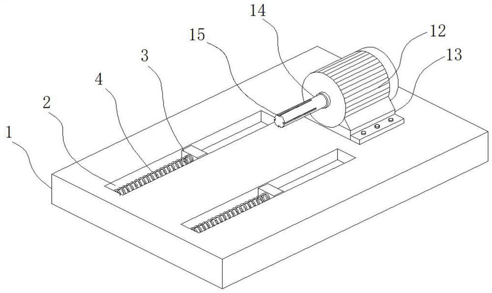
The invention provides a reciprocating type high-pressure plunger pump for oilfield exploitation water treatment. The reciprocating type high-pressure plunger pump comprises a high-pressure plunger pump body; the high-pressure plunger pump body comprises a bottom plate; a fixed groove is formed in the top of the bottom plate; a supporting block is mounted in the fixed groove; a supporting spring is mounted between the supporting block and the fixed groove; a fixed block is installed in the fixed groove; a fixed plate is welded to the top of the fixed block; a working part is installed at the top of the fixed plate; and the bottom of the working part is fixed to the fixed plate through a reinforcing rib plate. According to the reciprocating type high-pressure plunger pump for oilfield exploitation water treatment, an electric push rod pushes a movable plate on a movable rod to move in a pressurization cavity, the distance between the movable plate and a piston is changed through movement, and therefore the internal water pressurization pressure is adjusted, and use under different pressure conditions is met; and pressurizing cavities at multiple positions are matched for use, so that the functions are diversified.

Description

technical field [0001] The invention relates to the field of oilfield exploitation equipment, in particular to a reciprocating high-pressure plunger pump for oilfield exploitation water treatment. Background technique [0002] In the process of oilfield exploitation, high-pressure plunger pump equipment is required to work and use. The operating pressure of high-pressure plunger pump should generally be between 10MPa and 100MPa. For the purpose of the liquid, the mechanical energy of the prime mover is directly converted into the pressure energy of the conveying liquid through the pump. The capacity of the pump only depends on the volume change value of the working chamber and the number of changes per unit time, and has nothing to do with the discharge pressure in theory. In the existing The pressure state of the high-pressure plunger pump is fixed and cannot be adjusted during use, so it cannot be used in different situations. In addition, the existing equipment cannot be ...

Claims


Application Information

Patent Timeline
Patent Type & Authority Applications(China)
IPC IPC(8): F04B1/0536F04B53/10F04B53/16F04B53/22
CPCF04B53/16F04B53/22F04B1/0536F04B53/10F04B53/162
Inventor 唐恭平沈奎梁峰
Owner HUBEI PETROKH MACHINE MFG
Learn More