
Part cooling-rim sealing structure for step-by-step utilization of cooling airflow of gas turbine

A technology for cooling airflow and gas turbines, which is applied in the cooling of engines, turbines/propulsion devices, and engine components, etc. It can solve the problems of reducing turbine efficiency, cooling airflow loss, and increasing fuel consumption, achieving both safety and reduction Effect of cooling airflow loss and gap reduction

Active Publication Date: 2021-11-02
XI AN JIAOTONG UNIV
View PDF8 Cites 1 Cited by
  • Summary
  • Abstract
  • Description
  • Claims
  • Application Information

AI Technical Summary

Problems solved by technology

In order to ensure the reliability of high-temperature components, it is often necessary to cool and seal in multiple places. A large amount of cooling air flows into the high-temperature mainstream gas, which will inevitably cause serious cooling air loss, reduce turbine efficiency, and increase fuel consumption. The advantages of increasing the gas temperature at the turbine inlet

Method used


Image

  • Part cooling-rim sealing structure for step-by-step utilization of cooling airflow of gas turbine
  • Part cooling-rim sealing structure for step-by-step utilization of cooling airflow of gas turbine

Examples


Embodiment Construction

[0028] The embodiments of the present invention will be described in detail below in conjunction with the accompanying drawings. This embodiment is based on the technical solution of the present invention, and provides detailed implementation methods and specific operating procedures, but the scope of protection of the present invention is not limited to the following embodiments. .

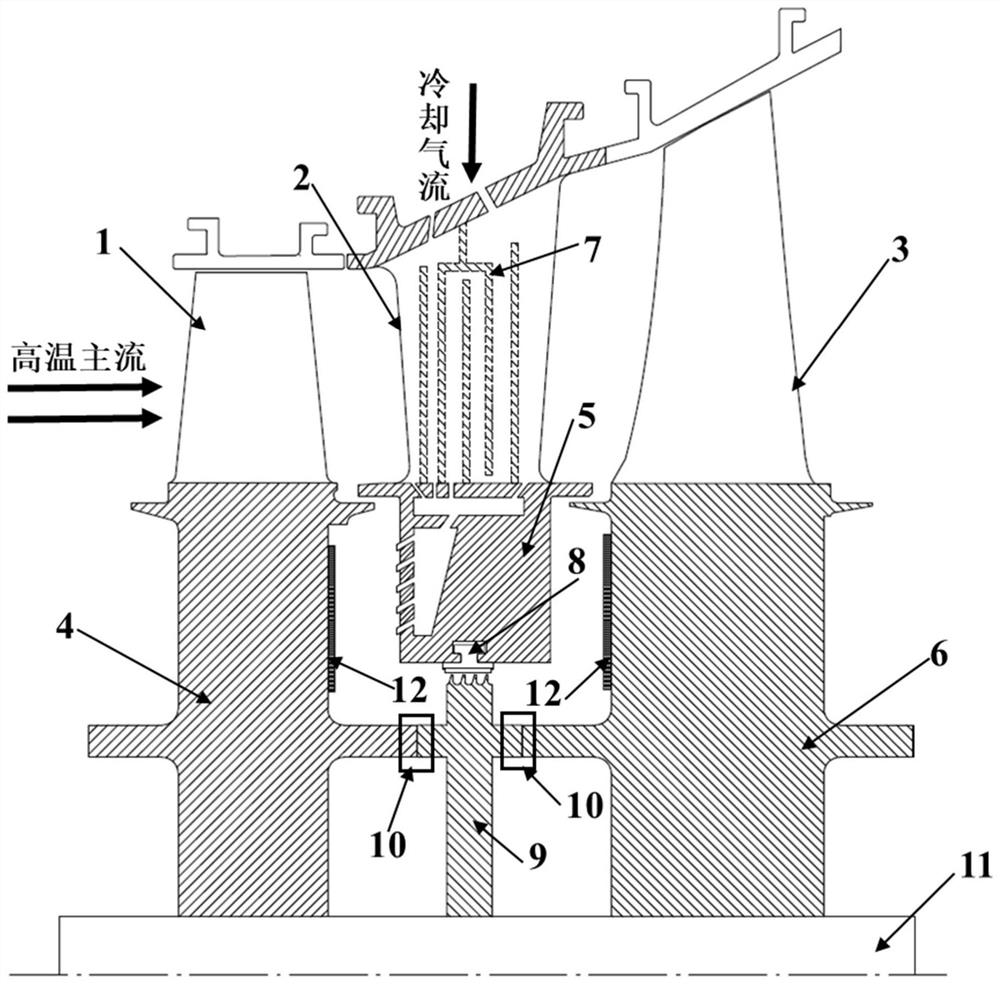
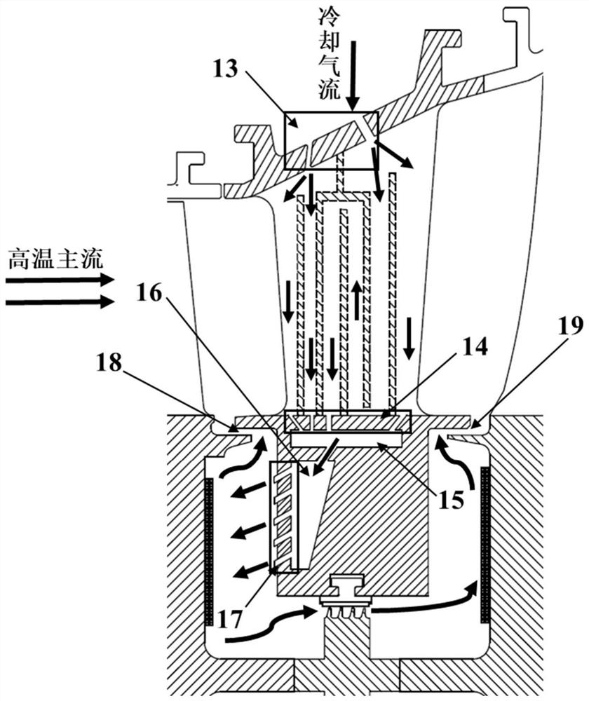
[0029] see figure 1 and figure 2 , a component cooling-rim sealing structure for the gas turbine cooling airflow to be utilized step by step provided by the present invention, including the stationary blade 2 and its stationary blade platform 5, the front stage moving blade 1 and the front stage moving blade disc 4, and the rear stage moving blade 3 and the latter stage moving blade disc 6, sealed stator 8, sealed rotor 9, and rotating shaft 11. The front-stage rotor blade 1 is connected to the front-stage rotor blade disc 4 through a blade root-rim structure, the front-stage rotor blade disc ...


PUM


Abstract

The invention discloses a part cooling-rim sealing structure for step-by-step utilization of cooling airflow of a gas turbine. The part cooling-rim sealing structure comprises a stationary blade, a stationary blade platform of the stationary blade, a front-stage moving blade, a front-stage moving blade disc and the like. A premixing chamber and an air distribution chamber are arranged in the stationary blade platform, cooling airflow in a blade flows into the premixing chamber through a cooling airflow outlet hole in the bottom of the stationary blade and then is jetted into a first rotor-stator chamber through a cooling airflow jet hole formed in the air distribution chamber, and one path of cooling airflow flows from inside to outside in the radial direction after cooling the front-stage moving blade disc and converges into a main flow through an upstream rim gap; and the other path of cooling airflow flows into a second rotor-stator cavity after being subjected to sealed cooling, depressurization and acceleration, and converges into the main flow through a downstream rim gap after cooling a rear-stage moving blade disc. According to the structure, the cold source characteristic of the cooling airflow is fully utilized step by step, the cooling airflow is used for sealing the rim gap after cooling each part, the temperature when the cooling airflow converges into the main flow is increased, the cold air loss is reduced, and the functions of part cooling and rim sealing are realized by utilizing the single-strand cooling airflow.

Description

technical field [0001] The invention belongs to the field of gas turbines, and in particular relates to a component cooling-wheel rim sealing structure in which the gas turbine cooling air flow is utilized step by step. Background technique [0002] Gas turbine components will produce thermoelastic deformation, centrifugal deformation, and shafting vibration under actual thermal operating conditions. In order to prevent contact and scratching between rotating parts and stationary parts, a gap value must be left between moving and static parts. When the internal pressure of the rotating disk cavity formed by the stationary blade diaphragm and the rotating turbine disk is lower than the mainstream pressure, gas intrusion will occur. The temperature gradient between the radius area and the inner diameter of the wheel increases, and the thermal stress of the wheel increases sharply, causing harmful deformation and, in severe cases, rupture of the wheel. In order to ensure the s...

Claims


Application Information

Patent Timeline
Patent Type & Authority Applications(China)
IPC IPC(8): F02C7/18F01D5/18F01D25/12
CPCF02C7/18F01D5/18F01D5/186F01D25/12Y02T50/60
Inventor 谢永慧施东波李冬李金星张荻
Owner XI AN JIAOTONG UNIV
Learn More