


Quick Research
Generate reliable direction feasibility study reports for your R&D in just a few steps.

Technical Q&A
Discover and master advanced knowledge NOW. Basics, ideas, possibilities, all at once.

Find Solutions
As an expert in R&D theories, this can generate solutions to your technical problems instantly.

Evaluate Feasibility
Analyze your overall solution with one click, know your potential R&D risks in advance.

Monitor Landscape
Get weekly tech updates, stay abreast of the latest tech innovations and key insights.
Concrete conveying device for building construction
A conveying device and a technology for building construction, which are applied in the direction of construction, building structure, and building material processing, can solve the problems of single concrete conveying and the inability to improve the efficiency of concrete pouring, and achieve easy disassembly and installation, smooth rotation, and improved The effect of work efficiency
- Summary
- Abstract
- Description
- Claims
- Application Information
AI Technical Summary
Problems solved by technology
Method used
Image

Examples
Embodiment 1
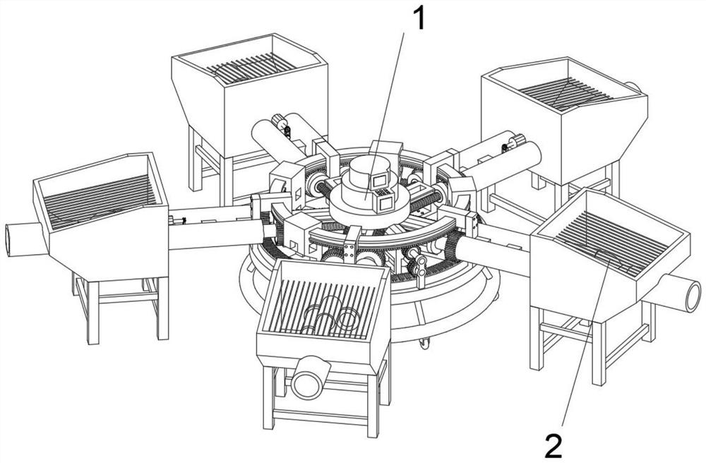
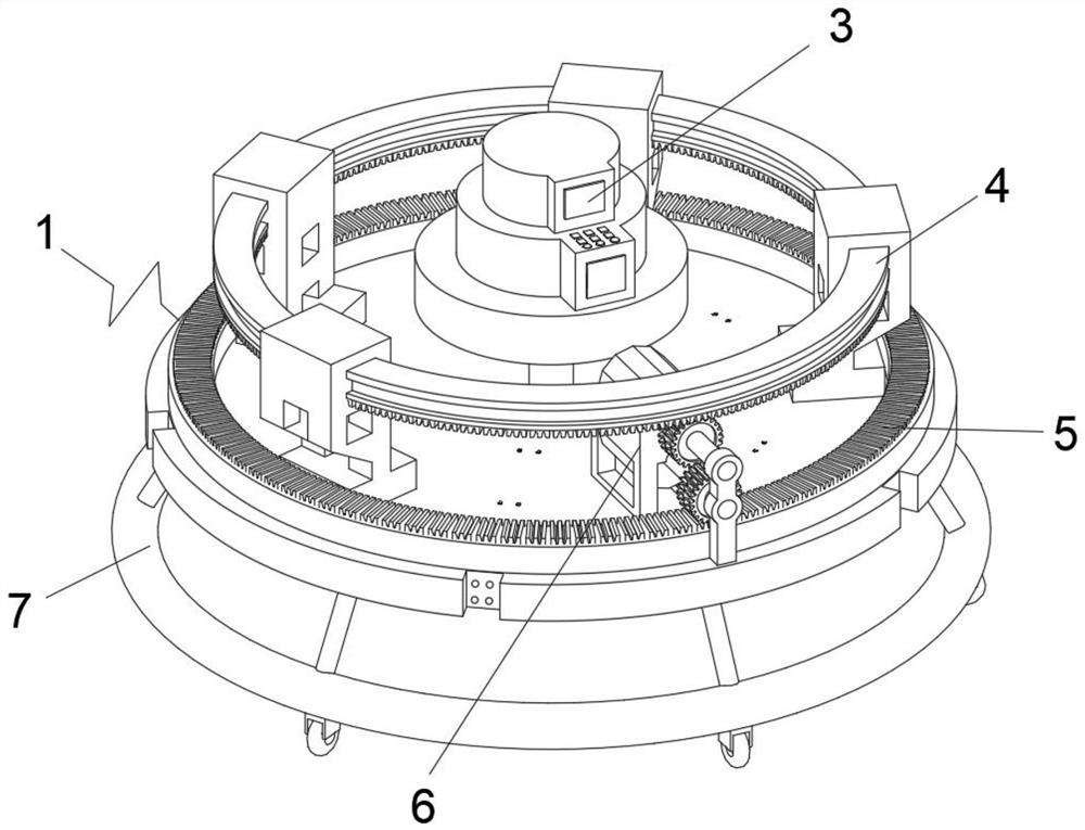
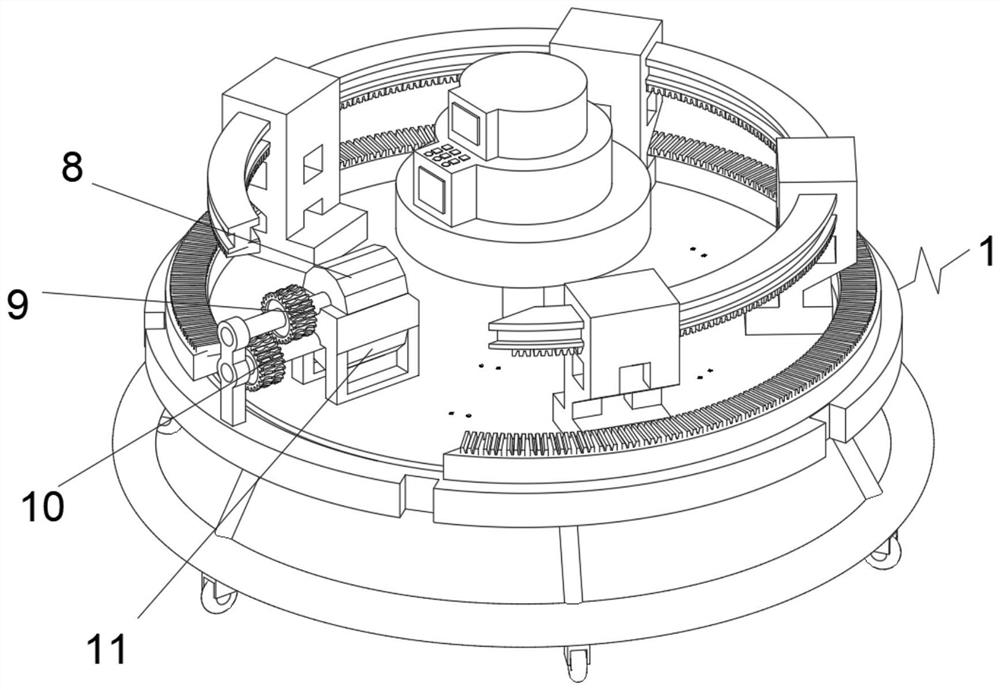
[0039] See Figure 1 - Figure 9In the present invention, the concrete conveying device of the construction is provided, including the driving device 1 and the conveying device 2, and the conveying device 2 is uniformly mounted on the top outer surface of the driving device 1, and the inside of the drive device 1 includes a controller 3. The transmission device 4, the first transmission tooth ring 5, the power device 6, the support seat 7, the first driving motor 8, the first driving gear 9, the second drive gear 10 and the second drive motor 11, the controller 3 slide insert At the center of the drive device 1, the first transmission tooth ring 5 is rotated mounted on the upper surface edge of the drive device 1, and the power device 6 is fixedly mounted on the upper surface of the drive device 1, and the support seat 7 is welded to the drive device 1. At the bottom edge, the transmission 4 is rotated mounted on the top edge of the driving device 1, and the second drive motor 11 is...
Embodiment 2
[0055] On the basis of Example 1, if Figure 10 As shown, the end surface center of the threaded push rod 22 is welded with a buckle block 35, and the center of the rubber column 21 is opened, and the second fastening screw 33 is attached to the side center spiral of the limit card block 34.
[0056] In the present embodiment, when the threaded push rod 22 is rotated from the rubber column 21 by the threaded push rod 22, it is easy to rotate or disassemble the threaded push rod 22, and the threaded push rod 22 can be rotated smoothly. It is convenient to disassemble the threaded pusher 22, and the limit card block 34 is tightened with the threaded pusher 22 by the second fastening screw 33, and the second fastening can be reversely rotated when the threaded pusher 22 is removed. The screw 33 disassembles the limit card block 34 to avoid the limit chuck 34 and the limit chute 25 phase card, which hinders the threaded pusher 22 to detach.
[0057] Working principle: When building con...
PUM
 Abstract
Description
Claims
Application Information
 - R&D Engineer
- R&D Manager
- IP Professional
- Industry Leading Data Capabilities
- Powerful AI technology
- Patent DNA Extraction
Browse by: Latest US Patents, China's latest patents, Technical Efficacy Thesaurus, Application Domain, Technology Topic, Popular Technical Reports.
© 2024 PatSnap. All rights reserved.Legal|Privacy policy|Modern Slavery Act Transparency Statement|Sitemap|About US| Contact US: help@patsnap.com