Lifting equipment for electromechanical installation

A lifting equipment, electromechanical technology, applied in the direction of hoisting equipment safety devices, lifting devices, etc., can solve the problems of personal safety of construction workers who are difficult to operate manually, and the quality of electromechanical equipment is heavy, so as to reduce personal safety, reduce manpower, and avoid manpower. The effect of electromechanical equipment

Pending Publication Date: 2021-11-02
武汉市鸿菱机电工程有限公司
View PDF13 Cites 0 Cited by
  • Summary
  • Abstract
  • Description
  • Claims
  • Application Information

AI Technical Summary

Problems solved by technology

[0004] The existing lifting devices for electromechanical installation generally place the electromechanical equipment on the lifting device, then control the lifting device to rise to a certain position, and then install it manually, but the existing lifting device can only transport the electromechanical equipment to a certain place. Then move the mechanical and electrical equipment to the installation position by manpower for alignment installation and other operations. However, most of the mechanical and electrical equipment is heavy, and it is difficult to operate manually, and a little carelessness in high-altitude operations will directly threaten the personal safety of construction personnel. In view of this , we propose a lifting device for electromechanical installation

Method used


Image

  • Lifting equipment for electromechanical installation
  • Lifting equipment for electromechanical installation
  • Lifting equipment for electromechanical installation

Examples


Embodiment Construction

[0023] The following description serves to disclose the present invention to enable those skilled in the art to carry out the present invention. The preferred embodiments described below are only examples, and those skilled in the art can devise other obvious variations.

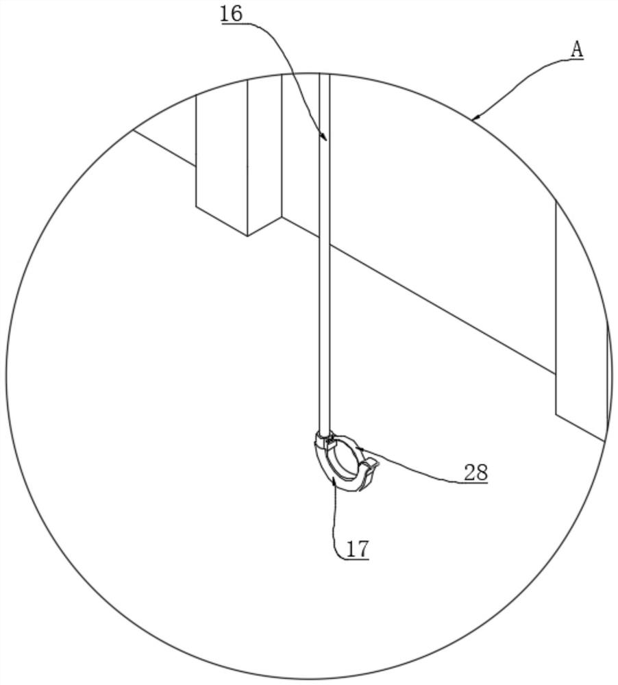
[0024] Such as Figure 1-8 The lifting equipment for electromechanical installation shown includes a lifting assembly 1 and an operating platform 2. The four corners of the upper surface of the operating platform 2 are respectively fixedly connected with supporting columns 3, and the tops of the two supporting columns 3 on the same side are fixedly connected with rectangular Frame 4, two first U-shaped grooves 5 are symmetrically opened on the inner side of the rectangular frame 4, and a rectangular mobile bracket 6 is arranged in the middle of the rectangular frame 4, and the mobile bracket 6 includes two first brackets 7 and two second The brackets 8 are rotatably connected to the opposite sides of the tw...


PUM


Abstract

The invention relates to the technical field of electromechanical installation, in particular to lifting equipment for electromechanical installation. The lifting equipment for electromechanical installation comprises a lifting assembly and an operating platform, wherein supporting columns are fixedly connected to four corners of the upper surface of the operating platform correspondingly, a rectangular frame is fixedly connected to the tops of the two supporting columns on the same side, and two first U-shaped grooves are symmetrically formed in the inner side surfaces of the rectangular frame. A rectangular moving support is arranged in the middle of the rectangular frame, the moving support comprises two first supports and two second supports, the sides, with the back towards each other, of the two first supports are rotationally connected with first rolling wheels, and each first rolling wheel is arranged in the corresponding first U-shaped groove in a rolling mode. According to the scheme, the electromechanical equipment is lifted through a driving motor and moved to the mounting position, so that the situation that the electromechanical equipment is carried manually, so that time and labor are wasted is avoided, and the problem of personal safety caused by carrying the electromechanical equipment by constructors is solved.

Description

technical field [0001] The invention relates to the technical field of electromechanical installation, in particular to a lifting device for electromechanical installation. Background technique [0002] The electromechanical installation lifting equipment is used to lift the installation objects, which is convenient for construction workers to install. [0003] Some patent documents related to electromechanical installation lifting equipment have been disclosed in the prior art. The Chinese patent application number 202021484329.7 discloses a special lifting equipment for electromechanical installation, including a bottom plate, a lifting structure is arranged above the bottom plate, and a lifting structure is installed on the upper end of the lifting structure. The carrying plate is fixed with a placing platform on the end surface of the carrying plate, and the side of the placing platform is provided with a first partition vertically fixed to it, and the side away from the...

Claims


Application Information

Patent Timeline
IPC IPC(8): B66F11/04B66F17/00
CPCB66F11/042B66F17/006
Inventor 冯细红
Owner 武汉市鸿菱机电工程有限公司
Why Eureka
Try Eureka