Screwer and device
A thread cutter and cutter head technology, which is applied in the field of thread processing, can solve the problems that affect processing efficiency and yield, and the processing threads are blocked and not straight, so as to achieve the effect of improving efficiency and yield, improving processing quality and processing accuracy
- Summary
- Abstract
- Description
- Claims
- Application Information
AI Technical Summary
Problems solved by technology
Method used
Image

Examples
Embodiment 1
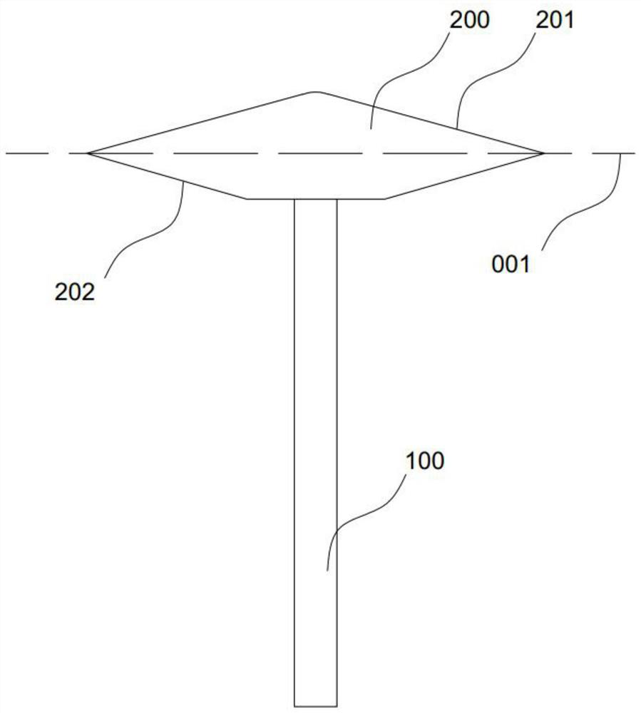
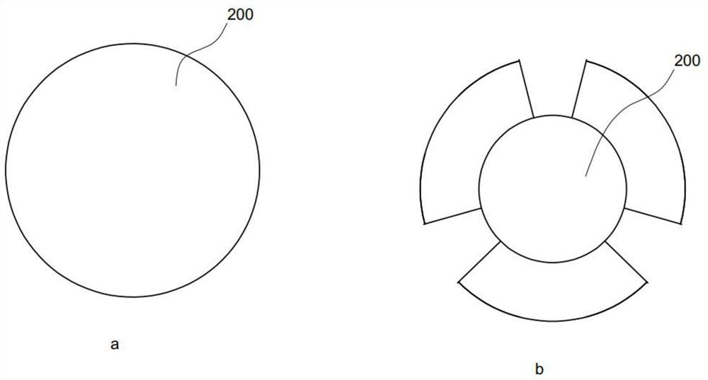
[0024] The screw cutter in the present embodiment comprises cutter bar 100 and cutter head 200, and cutter head 200 main body is nearly disc shape, as figure 2 As shown in a, the cutter head 200 is formed with a blade portion, and the blade portion includes a first blade surface 201 and a second blade surface 202, and the first blade surface 201 and the second blade surface 202 are two opposite surfaces of the disc and are oppositely arranged. The continuous blade structure formed at the circumferential position of the cutter head 200, the surface where the blade tip is formed by connecting the first blade surface 201 and the second blade surface 202 is the interface 001, and the angle between the first blade surface 201 and the interface 001 The angle between the second blade surface 202 and the interface 001 is 28°. The cutter head 200 includes a main body made of alloy and a brazing layer formed on the surface of the main body. The brazing layer includes abrasive disperse...
Embodiment 2
[0026] The screw cutter in this embodiment includes a cutter bar 100 and a cutter head 200. The cutter head 200 has a nearly disc-shaped main body. The cutter head 200 is formed with a blade, and the blade includes a first blade surface 201 and a second blade surface 202. The first blade surface 201 and the second blade surface 202 are two opposite faces of the disc and are arranged oppositely. The blade portion is formed in a continuous blade structure at the circumferential position of the cutter head 200, and is connected with the first blade surface 201 and the second blade surface 202. The surface where the blade edge is formed is the interface 001, the angle between the first blade surface 201 and the interface 001 is 28°, and the angle between the second blade surface 202 and the interface 001 is 27°. The cutter head 200 includes a main body made of alloy and a brazing layer formed on the surface of the main body. The brazing layer includes abrasive dispersed on the sur...
Embodiment 3
[0028] The thread cutter in this embodiment includes a cutter bar 100 and a cutter head 200. The cutter head 200 has a nearly disc-shaped main body and has a protruding three-point structure outside the circumference of the disc (that is, three protruding blades are formed, The three points here do not refer to the three equal parts in the strict mathematical sense. Reasonable deviations are allowed to meet the operating requirements of the thread cutter. Of course, three equal parts are the optimal solution), such as figure 2 As shown in b, the blade portion includes a first blade surface 201 and a second blade surface 202, so that the blade portion is formed as a discontinuous blade structure at the circumferential position of the cutter head 200, connected with the first blade surface 201 and the second blade surface 202 The surface where the blade tip is formed is the interface 001, the angle between the first blade surface 201 and the interface 001 is 27°, and the angle b...
PUM
 Abstract
Description
Claims
Application Information
 - R&D
- Intellectual Property
- Life Sciences
- Materials
- Tech Scout
- Unparalleled Data Quality
- Higher Quality Content
- 60% Fewer Hallucinations
Browse by: Latest US Patents, China's latest patents, Technical Efficacy Thesaurus, Application Domain, Technology Topic, Popular Technical Reports.
© 2025 PatSnap. All rights reserved.Legal|Privacy policy|Modern Slavery Act Transparency Statement|Sitemap|About US| Contact US: help@patsnap.com