
Iron filings distributing device for fastener processing

A material separating device and fastener technology, applied in the field of fastener processing, can solve the problems of insufficient iron filing effect, low efficiency, complicated operation process, etc., and achieve the effect of increasing the iron filing efficiency and high efficiency

Active Publication Date: 2021-12-03
南通市敦强紧固件制造有限公司
View PDF6 Cites 0 Cited by
  • Summary
  • Abstract
  • Description
  • Claims
  • Application Information

AI Technical Summary

Problems solved by technology

[0003] But the publication number is CN213377199U A kind of iron filings distributing device that is used for fastener processing, when carrying out iron filings distributing, first iron filings is carried out centralized collection, then shut down again and device is tilted, and iron filings is discharged, Then the fasteners are discharged. The whole operation process is very cumbersome and inefficient, and the iron filings are absorbed by the electromagnetic coil in the fasteners, and the iron filings are easily mixed into the fasteners during the stirring process. Therefore, the separation effect of iron filings is not good enough. Therefore, it is necessary to design an iron filing distributing device for fastener processing to realize rapid and sufficient distribution of iron filings and fasteners, and then directly separate and discharge the materials. Simple and efficient process

Method used


Image

  • Iron filings distributing device for fastener processing
  • Iron filings distributing device for fastener processing
  • Iron filings distributing device for fastener processing

Examples


Embodiment Construction

[0028] The following will clearly and completely describe the technical solutions in the embodiments of the present invention with reference to the accompanying drawings in the embodiments of the present invention. Obviously, the described embodiments are only some, not all, embodiments of the present invention.

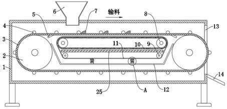
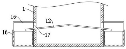
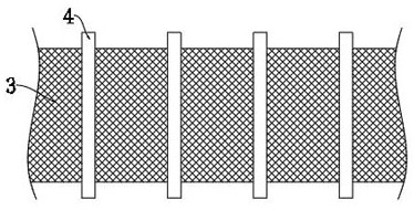
[0029] refer to Figure 1-6 , an iron chip distributing device for fastener processing, including a box body 1, feet are provided at the four corners of the bottom of the box body 1, a feed hopper 6 is provided on the top side of the box body 1, and the box body 1 is far away from the feeder. The side wall of the hopper 6 is provided with a fastener outlet 13, and the side wall of the box body 1 is fixed with a fastener discharge plate 14 corresponding to the position of the fastener outlet 13, and the fastener discharge plate 14 It is obliquely arranged below the fastener outlet 13, and the inside of the box body 1 is horizontally provided with two first roller shaf...


PUM


Abstract

The invention discloses an iron chip distributing device for fastener processing, which comprises a box body, a feeding hopper is arranged on the top side of the box body, and a feeding hopper is arranged on the side wall of the box body away from the feeding hopper. Fastener outlet, the inside of the box is horizontally provided with two first rollers, the two first rollers are covered with mesh belts, and the inner walls of both sides of the box are equipped with mesh belts. Vibrate during the feeding process, and flip the fasteners on the mesh belt to fully separate the fasteners from the iron filings. The first roller shaft near the outlet of the fasteners extends out of the fasteners At the exit, two second rollers are arranged horizontally between the two first rollers, and rubber tapes are set on the two second rollers. The invention can quickly separate the fasteners from the iron filings, and directly separate and discharge the fasteners from the iron filings, which greatly increases the separation efficiency of the iron filings, and can fully vibrate and separate the iron filings, further improving the separation effect of the iron filings .

Description

technical field [0001] The invention relates to the technical field of fastener processing, in particular to an iron chip distributing device for fastener processing. Background technique [0002] Fasteners are a type of mechanical parts that are used for fastening connections and are widely used. Fasteners are used in a wide range of industries, including energy, electronics, electrical appliances, machinery, chemicals, molds, hydraulic pressure and other industries. The fasteners will be mixed with iron filings during their production and processing. Therefore, it is necessary to use an iron filings distributing device to distribute and remove the iron filings mixed in the fasteners. [0003] But the publication number is CN213377199U A kind of iron filings distributing device that is used for fastener processing, when carrying out iron filings distributing, first iron filings is carried out centralized collection, then shut down again and device is tilted, and iron filing...

Claims


Application Information

Patent Timeline
Patent Type & Authority Patents(China)
IPC IPC(8): B03C1/30B65G15/54B65G23/44
CPCB03C1/30B65G15/54B65G23/44
Inventor 沙敦
Owner 南通市敦强紧固件制造有限公司
Learn More