Camera module, assembling method thereof and electronic equipment
A camera module and electrical connection technology, applied in the field of lenses, can solve the problems of complex electrical connection lines for adjustable lenses and high difficulty in the assembly process of the camera module, and achieve the effects of low assembly process difficulty and simplified electrical connection lines.
- Summary
- Abstract
- Description
- Claims
- Application Information
AI Technical Summary
Problems solved by technology
Method used
Image
Examples
Embodiment 1
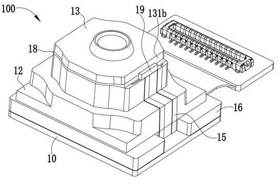
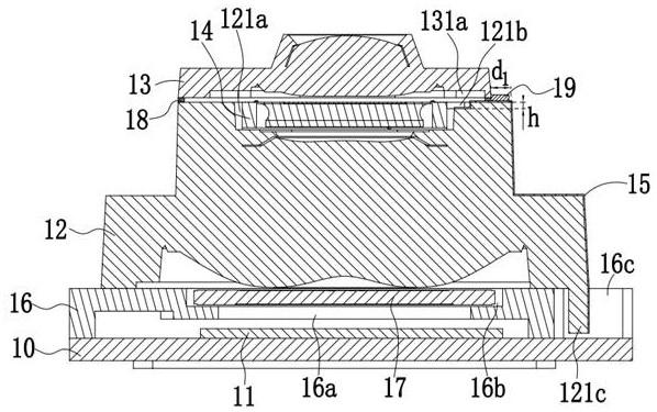
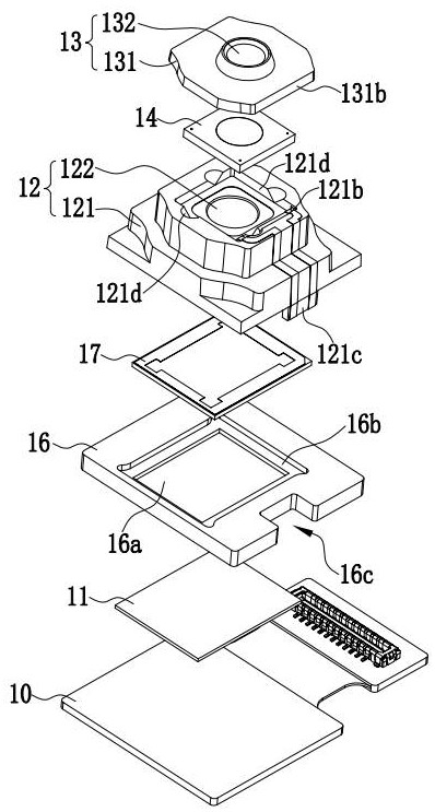
[0063] Please also refer to Figure 1 to Figure 3 , is a schematic structural diagram of a camera module 100 provided in Embodiment 1 of the present invention, the camera module 100 includes a substrate 10, a photosensitive element 11, a first mirror group 12, a second mirror group 13, and an adjustable lens 14 And the metal circuit layer 15, the photosensitive element 11 is arranged on the substrate 10, the first lens group 12 includes a first lens barrel 121 and a first lens group 122 installed on the first lens barrel 121, the first lens barrel 121 Set on the substrate 10, the image-side end of the first lens barrel 121 faces the photosensitive element 11, the end surface of the object-side end of the first lens barrel 121 is provided with a first accommodation groove 121a, and the second lens group 13 includes a second lens barrel 131 and The second lens group 132 installed in the second lens barrel 131, the second lens barrel 131 is arranged on the object side end of the ...
Embodiment 2
[0092] Please also refer to Figure 6 , is a schematic structural diagram of an electronic device 200 provided in Embodiment 2 of the present invention. The electronic device 200 includes a device main body 20 and the camera module 100 of Embodiment 1. The camera module 100 is disposed on the device main body 20 .
[0093] Exemplarily, the electronic device 200 in this embodiment may be a mobile phone, a tablet computer, a camera, a surveillance probe, and the like. The camera module 100 can be fixed or movable on the main body 20 of the device. When the electronic device 200 is a mobile phone or a tablet, the camera module 100 can be a front camera module or a rear camera module of the phone or tablet.
[0094] Embodiment 2 of the present invention provides an electronic device 200, the electrical connection circuit of the adjustable lens of the camera module 100 is relatively simple, and the assembly process of the camera module 100 is less difficult.
Embodiment 3
[0096] see Figure 7 , is a schematic flowchart of a camera module assembly method provided by Embodiment 3 of the present invention. The assembly method is applied to the camera module of Embodiment 1. The specific structure of the camera module can refer to Embodiment 1, and will not be described again. The assembly method includes the following steps:
[0097] S301 , installing the photosensitive element on the substrate.
[0098] It can be understood that, by implementing step S301, the photosensitive element is fixed on the substrate, and the photosensitive element is electrically connected to the substrate.
[0099] S302. Install the adjustable lens into the first receiving slot, and electrically connect the adjustable lens to the metal circuit layer.
[0100] It should be known that this assembly method is applied to the camera module in Embodiment 1. It can be seen from Embodiment 1 that the adjustable lens is connected to the first receiving groove by bonding, then ...
PUM
| Property | Measurement | Unit |
|---|---|---|
| Surface roughness | aaaaa | aaaaa |
| Thickness | aaaaa | aaaaa |
| Thickness | aaaaa | aaaaa |
Abstract
Description
Claims
Application Information
 - R&D Engineer
- R&D Manager
- IP Professional
- Industry Leading Data Capabilities
- Powerful AI technology
- Patent DNA Extraction
Browse by: Latest US Patents, China's latest patents, Technical Efficacy Thesaurus, Application Domain, Technology Topic, Popular Technical Reports.
© 2024 PatSnap. All rights reserved.Legal|Privacy policy|Modern Slavery Act Transparency Statement|Sitemap|About US| Contact US: help@patsnap.com


