
Radar synthetic aperture sparse imaging method and system using slide rail

A sparse imaging and synthetic aperture technology, applied in the field of radar target detection and recognition, can solve problems such as inapplicability, high imaging cost, and limited application of airborne SAR, so as to reduce computational complexity, improve resolution, and achieve azimuth focusing Effect

Pending Publication Date: 2021-10-29
NAVAL AVIATION UNIV
View PDF0 Cites 0 Cited by
  • Summary
  • Abstract
  • Description
  • Claims
  • Application Information

AI Technical Summary

Problems solved by technology

[0003] At present, SAR is mainly used for the imaging of stationary targets by moving platforms, mainly for the imaging of large-scale scene targets by airborne platforms, and the imaging cost is very high. For the imaging of targets in small areas, the application of airborne SAR is relatively limited and not applicable

Method used


Image

  • Radar synthetic aperture sparse imaging method and system using slide rail
  • Radar synthetic aperture sparse imaging method and system using slide rail
  • Radar synthetic aperture sparse imaging method and system using slide rail

Examples


Embodiment 1

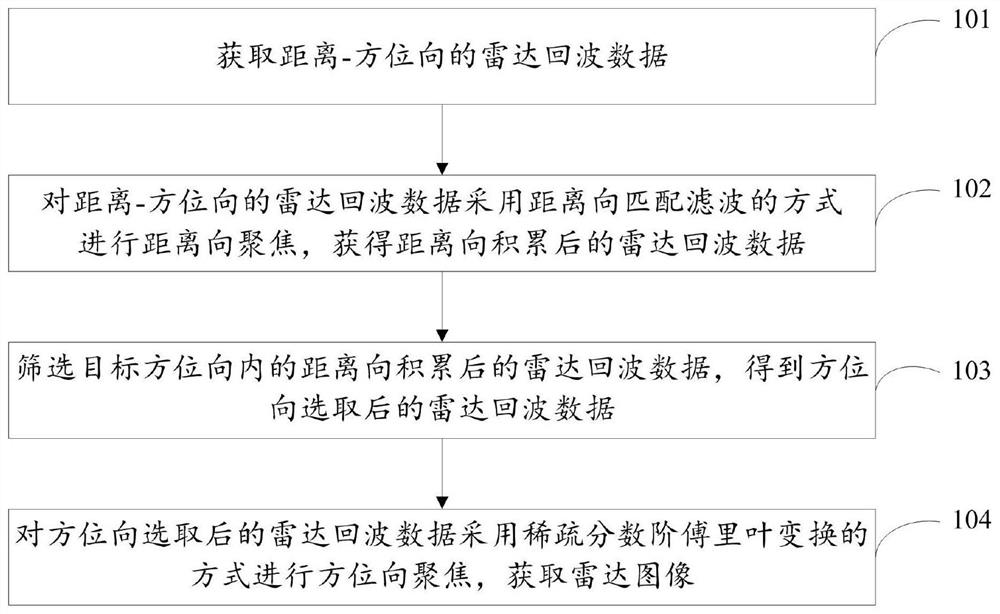
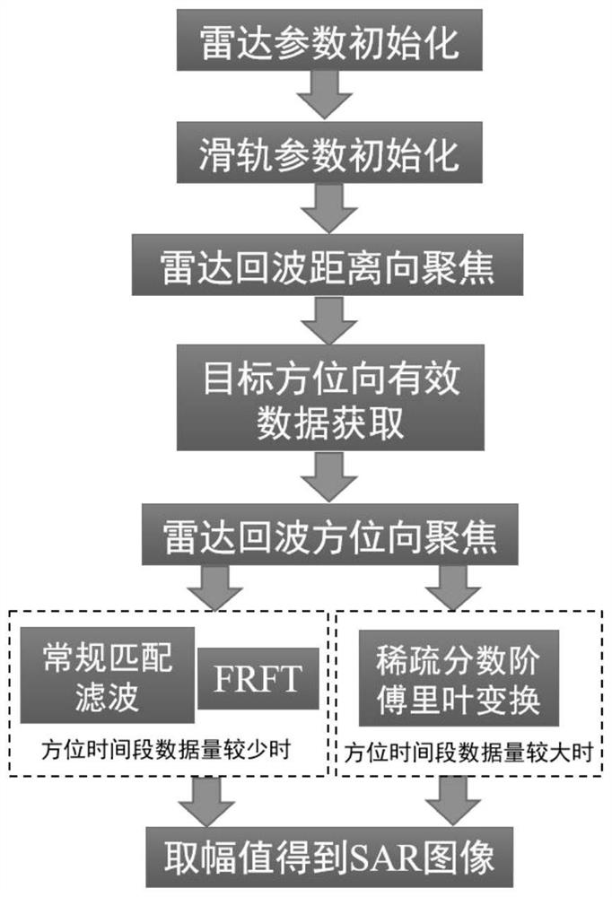
[0065] Such as figure 1 and 2 As shown, the present invention provides a radar synthetic aperture sparse imaging method utilizing slide rails, said method comprising the steps of:

[0066] Step 101, acquiring radar echo data in the range-azimuth direction.

[0067] The acquisition of the radar echo data in the range-azimuth direction in step 101 specifically includes:

[0068] Set the radar on the slide rail so that the beam of the radar faces the target to be imaged.

[0069] The radar is controlled to transmit signals while sliding on the slide rail, and the radar echo data in the range-azimuth direction is acquired.

[0070] The specific steps are:

[0071] Radar parameter initialization, frequency modulation continuous wave radar set modulation bandwidth, modulation period, sampling frequency, transmit signal waveform and other parameters; pulse radar set signal bandwidth, repetition period, sampling frequency, transmit waveform and other parameters.

[0072] Initiali...

Embodiment 2

[0132] The present invention also provides a radar synthetic aperture sparse imaging system utilizing slide rails, the system comprising:

[0133] The radar echo data acquisition module is used to acquire the radar echo data in the range-azimuth direction.

[0134] The radar echo data acquisition module specifically includes: an initialization sub-module for setting the radar on the slide rail so that the radar beam is directed towards the target to be imaged; a radar echo data acquisition sub-module for controlling the radar in the Transmit signals while sliding on the slide rail, and obtain radar echo data in the range-azimuth direction.

[0135] The radar echo data in the range-azimuth direction is:

[0136]

[0137] Among them, t is the fast time, representing the distance dimension, t m is the slow time, representing the azimuth dimension, s r (t,t m ) is the radar echo data in the range-azimuth direction, A r is the amplitude of the radar echo data in the distanc...

Embodiment 3

[0142] In order to illustrate the technical effects of the present invention, the present invention also provides the following specific examples to illustrate the present invention.


PUM


Abstract

The invention relates to a radar synthetic aperture sparse imaging method and system using a slide rail. The method comprises the following steps of obtaining radar echo data of a range-azimuth direction, performing range focusing on the range-azimuth radar echo data by adopting a range matched filtering mode to obtain radar echo data after range accumulation, screening the radar echo data accumulated in the target azimuth direction in the range direction, and acquiring the radar echo data after azimuth direction selection, and carrying out azimuth focusing on the radar echo data after azimuth selection by adopting a sparse fractional order Fourier transform mode to obtain a radar image. According to the method, the sparse fractional order Fourier transform method is adopted, azimuth focusing is achieved, the resolution is improved, and the calculation complexity is reduced to a large extent.

Description

technical field [0001] The invention relates to the technical field of radar target detection and recognition, in particular to a radar synthetic aperture sparse imaging method and system using slide rails. Background technique [0002] With the development of the radar system, people continue to pursue the high resolution of the radar to meet the needs of discrimination and recognition of the target. Modern high-resolution microwave imaging technology is mainly based on Synthetic Aperture Radar (SAR), which is characterized by placing radar equipment on carrier platforms such as aircraft or satellites, and launching and Receive electromagnetic waves. The obtained echoes are subjected to complex 2D signal processing to obtain high-resolution radar images. [0003] At present, SAR is mainly used for the imaging of stationary targets by moving platforms, mainly for the imaging of large-scale scene targets by airborne platforms, and the imaging cost is very high. For the imag...

Claims


Application Information

Patent Timeline
Patent Type & Authority Applications(China)
IPC IPC(8): G01S13/90
CPCG01S13/9021
Inventor 陈小龙薛永华张海袁豆豆张财生张林黄勇
Owner NAVAL AVIATION UNIV
Learn More