A test device for loading a bridge chain rake

A test device and bridge chain technology, which is applied in the field of test devices loaded with bridge chain rakes, can solve the problems of long test period, long time for products to be introduced to the market, and great influence of crop planting seasons, etc., and achieve high guiding value Effect

Active Publication Date: 2021-12-21
LOVOL HEAVY IND CO LTD
View PDF10 Cites 0 Cited by
  • Summary
  • Abstract
  • Description
  • Claims
  • Application Information

AI Technical Summary

Problems solved by technology

[0002] At present, field tests are mainly carried out for crossing the bridge, and the service life of the conveyor chain cannot be compared with the same working conditions.
In addition, the field test is greatly affected by the crop planting season, and the test period is long, resulting in a long time for the product to be introduced to the market

Method used


Image

  • A test device for loading a bridge chain rake
  • A test device for loading a bridge chain rake
  • A test device for loading a bridge chain rake

Examples


Embodiment Construction

[0034] The principles and features of the present invention will be described below with reference to the accompanying drawings, and the exemplary examples are intended to be construed as not intended to limit the scope of the invention.

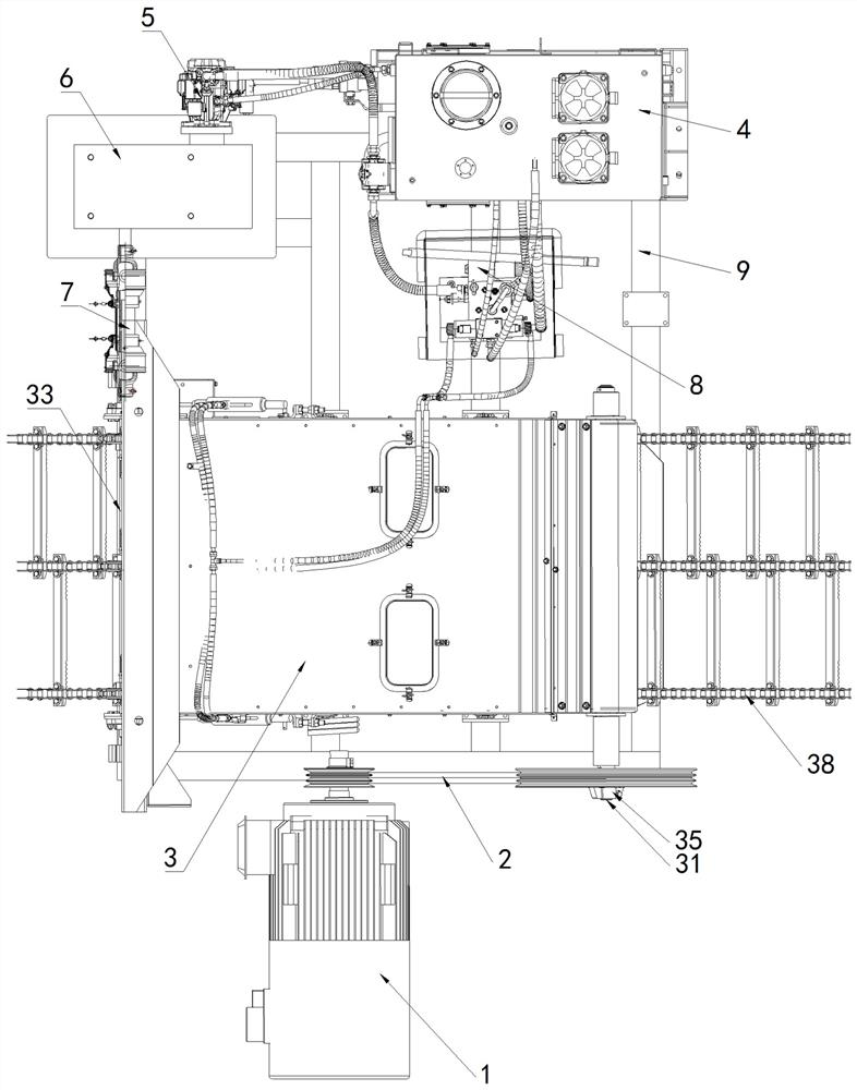
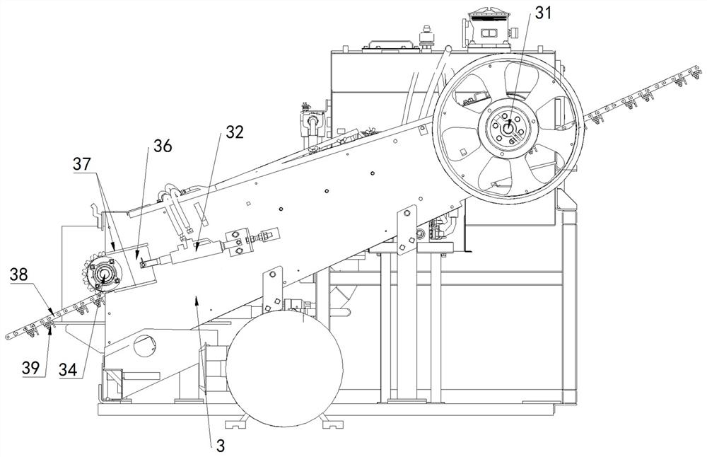
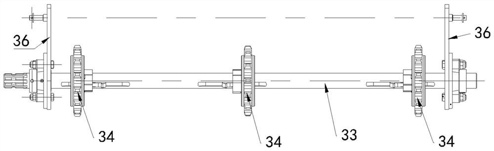
[0035] like Figure 1 ~ 5 As shown, a test device for transitioning the bridge chain load, including a motor 1, a bridge drive shaft 31, a bridge main body 3, a carrier shaft 33, and a hydraulic loading system, the overlapping active shaft 31 And the loading shaft 33 is mounted on the bridge main body 3, and the motor 1 is driven by the transmission belt 2 and the overlapping active shaft 31, which is attached to the overlapping active shaft 31, which is installed on a secure clutch 35. The bridge active shaft 31 operates by driving the shuttle roller 311, the conveying chain 38 is simultaneously engaged with the loading shaft 33; the hydraulic loading system passes through the transmission shaft 7 and the loading shaft 33 connect.

[0036] Speci...


PUM


Abstract

The invention relates to a test device for loading a bridge chain rake, which belongs to the related technical field of agricultural machinery. The test device includes a motor, a bridge drive shaft, a bridge body, a loading shaft, and a hydraulic loading system. The bridge drive shaft and the loading shaft are respectively installed on the bridge body. The motor is connected to the bridge drive shaft through a transmission belt. A safety clutch is installed on the driving shaft, and the bridge driving shaft drives the conveyor chain of the bridge chain rake through the driving sprocket, and the conveyor chain meshes with the loading shaft at the same time; the hydraulic loading system is connected to the loading shaft through the transmission shaft. Through the hydraulic loading system, the loading shaft is loaded with different loads experienced during field operations, which can realize rapid loading tests and simulate extreme working conditions, provide resistance for the operation of the conveyor chain, and test the service life of the conveyor chain. To confirm the reliability and load-carrying performance of the bridge chain rake conveyor chain and check the wear degree of each component.

Description

Technical field [0001] The present invention relates to a bridge-related technique, and more particularly to a test device for a bridge chain loading loading. Background technique [0002] At present, the bridge mainly performs field trials, and the service life of the conveying chain cannot be compared with the same conditions. In addition, the field test is greatly affected by the seasons of the trend, and the test cycle is longer, resulting in a longer product push market time. Inventive content [0003] The technical problem to be solved by the present invention is for the prior art insufficient, providing a test device for crossing the bridge chain loading. [0004] The present invention solves the technical solutions of the above technical problems as follows: a test device for crossing the bridge chain load, including a motor, a bridge active shaft, a bridge body, a loading shaft, and a hydraulic loading system, the overlapping active shaft and The load shaft is mounted o...

Claims


Application Information

Patent Timeline
Patent Type & Authority Patents(China)
IPC IPC(8): G01M13/023G01M13/025G01M13/027
CPCG01M13/023G01M13/025G01M13/027
Inventor 杨志广张克岩周丹丹张玉增张争旭李部
Owner LOVOL HEAVY IND CO LTD
Why Eureka
Try Eureka