Drill rod mud scraper

A mud scraper and drill pipe technology, which is applied in the direction of drilling tools, drilling equipment, earthwork drilling, etc., can solve the problems that affect the working safety of the staff, the mud scraper is stuck, and the mud scraper is easy to wear, so as to improve the scraper Mud effect, prevent scratches, ensure the effect of normal rotation

Active Publication Date: 2021-10-29
SHENGLI OILFIELD DONGRUN MACHINERY ENG
View PDF9 Cites 1 Cited by
  • Summary
  • Abstract
  • Description
  • Claims
  • Application Information

AI Technical Summary

Problems solved by technology

[0002] In the process of drilling an oil well, it is often necessary to take out the drilling tool from the oil well to check the drilling tool or connect the drill pipe. During the process of taking out the drilling tool, due to the mud attached to the drill pipe, when the drill pipe is taken out , the mud and well fluid will be scattered on the workbench near the wellhead driven by the drill pipe, which will cause the workbench to be slippery and affect the working safety of the staff. In order to prevent the mud and well fluid from splashing, when the drilling tool is taken out, A mud scraper will be installed on the drill pipe near the wellhead, so that the mud and well fluid attached to the drill pipe can fall back into the oil well under the action of the mud scraper
[0003] The existing mud scraper is generally a rubber disc with a relatively simple structure, and the existing mud scraper is static when scraping the drill pipe, and there is more mud on the surface of the drill pipe. During the removal process, the mud is easy to adhere to the bottom of the mud scraper, which will cause the mud scraper to be stuck. In addition, because the mud scraper and the surface of the drill pipe are closely bonded, after a long time of mud scraping operation , the inner side of the mud scraper is easy to wear, so that the worn part of the mud scraper does not have a good scraping effect on the drill pipe

Method used


Image

  • Drill rod mud scraper
  • Drill rod mud scraper
  • Drill rod mud scraper

Examples


Embodiment Construction

[0030] In order to make the purpose, technical solutions and advantages of the embodiments of the present invention more clear, the technical solutions in the embodiments of the present invention will be clearly and completely described below in conjunction with the accompanying drawings in the embodiments of the present invention. Obviously, the described embodiments It is a part of embodiments of the present invention, but not all embodiments. Based on the embodiments of the present invention, all other embodiments obtained by persons of ordinary skill in the art without making creative efforts belong to the protection scope of the present invention.

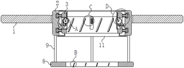
[0031] The present invention provides such Figure 1-7 A drill pipe mud scraper shown includes a pressure plate 1, a casing 2 is inserted through the top of the pressure plate 1, a movable pipe 3 is arranged inside the casing 2, and a movable pipe 3 is fixedly connected to the outside of the movable pipe 3. Two spacer rings 4...


PUM


Abstract

The invention belongs to the technical field of oil drilling, and particularly relates to a drill rod mud scraper. The drill rod mud scraper comprises a pressing plate, a sleeve is inserted into the top of the pressing plate in a penetrating mode, a movable pipe is arranged on the inner side of the sleeve, two limiting rings are fixedly connected to the outer side of the movable pipe, annular limiting grooves are formed in the positions, corresponding to the limiting rings, of the inner side of the sleeve, the limiting rings are located in the limiting grooves, and a plurality of mounting holes are formed in the inner wall of the movable pipe in a penetrating mode. Through the arrangement of the sleeve, in the upward movement process of a drill rod, a roller drives a shifting rod to make contact with a shifting plate under the action of the drill rod through the transmission action of a first gear belt and a second gear, so that the movable pipe drives a first scraper blade on the inner side of the movable pipe to conduct annular mud scraping operation on the surface of the drill rod under the cooperation action of the shifting rod and the shifting plate; and the movable pipe is always in a rotating state, so that the slurry is not easy to attach to the bottom of the movable pipe and the first scraper blade, and the normal work of the first scraper blade is further ensured.

Description

technical field [0001] The invention belongs to the technical field of petroleum drilling, in particular to a mud scraper for drilling pipes. Background technique [0002] In the process of drilling an oil well, it is often necessary to take out the drilling tool from the oil well to check the drilling tool or connect the drill pipe. During the process of taking out the drilling tool, due to the mud attached to the drill pipe, when the drill pipe is taken out , the mud and well fluid will be scattered on the workbench near the wellhead driven by the drill pipe, which will cause the workbench to be slippery and affect the working safety of the staff. In order to prevent the mud and well fluid from splashing, when the drilling tool is taken out, A mud scraper will be fitted on the drill pipe near the wellhead, so that the mud and well fluid attached to the drill pipe can fall back into the oil well under the action of the mud scraper. [0003] The existing mud scraper is gene...

Claims


Application Information

Patent Timeline
Patent Type & Authority Applications(China)
IPC IPC(8): E21B12/06
CPCE21B12/06
Inventor 刘钦
Owner SHENGLI OILFIELD DONGRUN MACHINERY ENG
Why Eureka
Try Eureka