
Patsnap Eureka
For R&D, Patsnap Eureka makes reading and utilizing patents & technical documents easy.
Patsnap Eureka AIR
Designed for self-driven R&D workflows. Generate viable solutions, solve complex R&D challenges, empower your innovation with AI.

Patsnap Eureka Materials
Designed for material experts only. Revolutionize your material R&D, from search, analyze, to developing new materials.

TechResearch
Generate reliable direction feasibility study reports for your R&D in just a few steps.

TechSeek
Discover and master advanced knowledge NOW. Basics, ideas, possibilities, all at once.

TechMind
As an expert in R&D Theories, TechMind can generates customized viable solutions instantly.

TechRisk
Analyze your overall solution with one click, know your potential R&D risks in advance.

TechMonitor
Get weekly tech updates, stay abreast of the latest tech innovations and key insights.
Spraying device facilitating adjustment of powder supply amount for cast iron pipeline
A spraying device and pipeline technology, applied in the direction of spraying devices, liquid spraying devices, etc., can solve problems such as difficulty in grasping the amount of powder sprayed, uneven powder spraying, powder waste, etc., to save manpower and material resources, comprehensive powder spraying, and avoid waste Effect
- Summary
- Abstract
- Description
- Claims
- Application Information
AI Technical Summary
Problems solved by technology
Method used
Image

Examples
Embodiment 1
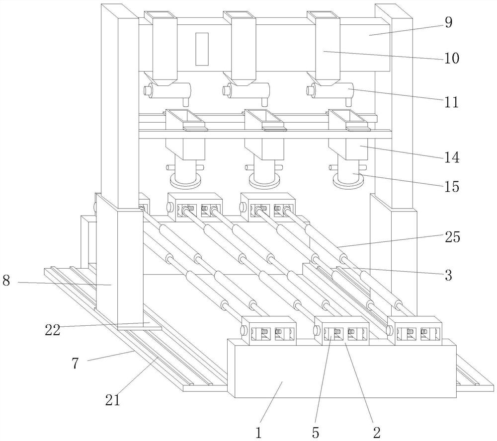
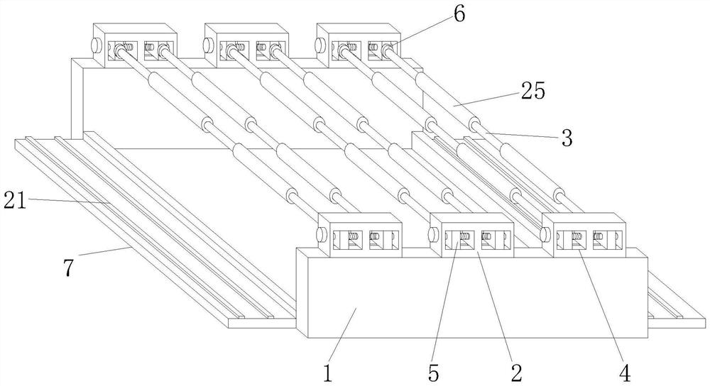
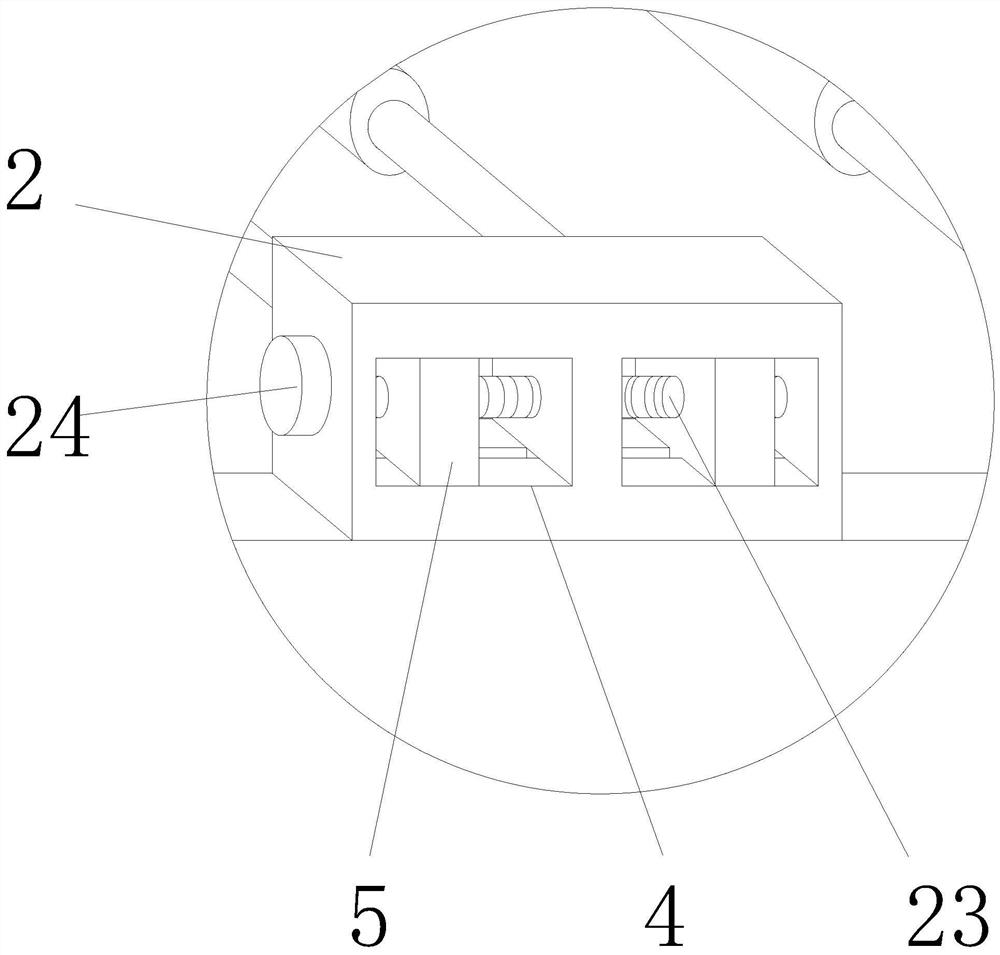
[0027] according to figure 1 , 2 , 3, 4, and 5, this embodiment proposes a spraying device for cast iron pipelines that is convenient for adjusting the powder supply, including a rolling assembly and a powder spraying assembly, and the powder spraying assembly includes a frame 1 and is located on the frame 1 rolling unit, the rolling unit includes the mounting block 2 and the rotating shaft 3 at the front and rear ends, both sides of the mounting block 2 are provided with chute 4, and the insides of the two sets of chute 4 are movably installed by the drive part There is a slider 5, the rotating shaft 3 is installed between the sliders 5 at the front and rear ends, and the slider 5 at the rear end is provided with a first motor 6, and the output end of the first motor 6 is connected to the rotating shaft 3 connected, the two sets of rotating shafts 3 in the rolling unit rotate synchronously and in the same direction;
[0028] Both sides of the frame 1 are provided with a sup...
Embodiment 2
[0036] according to figure 1 , 2, 4, the present embodiment proposes a spraying device for a cast iron pipeline that is convenient for adjusting the powder supply, including a rolling assembly and a powder spraying assembly, and the powder spraying assembly includes a frame 1 and a rolling unit arranged on the frame 1, The rolling unit includes a mounting block 2 and a rotating shaft 3 at the front and rear ends. Both sides of the mounting block 2 are provided with chute 4, and the insides of the two sets of chute 4 are movably installed with sliders 5 through the driving part. , the rotating shaft 3 is rotatably installed between the sliders 5 at the front and rear ends, and the slider 5 at the rear end is provided with a first motor 6, the output end of the first motor 6 is connected to the rotating shaft 3, and the The two groups of rotating shafts 3 in the rolling unit rotate synchronously and in the same direction;
[0037] Both sides of the frame 1 are provided with a ...
PUM
 Abstract
Description
Claims
Application Information
 - R&D Engineer
- R&D Manager
- IP Professional
- Industry Leading Data Capabilities
- Powerful AI technology
- Patent DNA Extraction
Browse by: Latest US Patents, China's latest patents, Technical Efficacy Thesaurus, Application Domain, Technology Topic, Popular Technical Reports.
© 2024 PatSnap. All rights reserved.Legal|Privacy policy|Modern Slavery Act Transparency Statement|Sitemap|About US| Contact US: help@patsnap.com