Electric connector

A technology of electrical connectors and connecting parts, which is applied in the direction of connection and connection device components, circuits, etc., and can solve the problem of affecting the mutual conduction of shielding members 916, affecting the high-frequency performance of electrical connectors, and unstable structures of electrical connectors, etc. problems, to improve the shielding effect, reduce signal crosstalk, and ensure electrical continuity

Active Publication Date: 2021-10-26
中山得意电子有限公司
View PDF9 Cites 0 Cited by
  • Summary
  • Abstract
  • Description
  • Claims
  • Application Information

AI Technical Summary

Problems solved by technology

[0003] However, in this electrical connector, the plurality of modules 910 are only assembled together through the protrusion 912 and the recess 914 of the shielding member 916, and the plurality of modules 910 are easily separated, resulting in The structure of the electrical connector is not stable; and the shielding members 916 of the three modules 910 located on the same sheet 754A-754D are in contact with each other through the protruding portion 912, which is easy to be caused by the gap between the protruding portion 912 and the concave portion 914. There is an error in the matching size between the multiple shielding members 916, which will affect the contact between the multiple shielding members 916, and poor contact will easily occur, affecting the mutual conduction between the multiple shielding members 916, and between the multiple shielding members 916 except There will be assembly gaps in the rest of the protruding part 912 and the recessed part 914, so that the conductive elements 925, 935 in the multiple modules 910 have signal crosstalk, thereby affecting the high-frequency performance of the electrical connector.

Method used


Image

  • Electric connector
  • Electric connector
  • Electric connector

Examples


Embodiment Construction

[0033] In order to facilitate a better understanding of the purpose, structure, features, and effects of the present invention, the present invention will now be further described in conjunction with the accompanying drawings and specific embodiments.

[0034] In order to make it easier to understand the technical solution of the present invention, the X-axis in the three-dimensional coordinate axes in the accompanying drawings is defined as the first direction, the Z-axis is defined as the second direction, the Y-axis is defined as the third direction, and the X-axis, Y-axis and Two pairs of Z axes are perpendicular to each other.

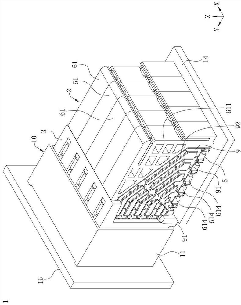
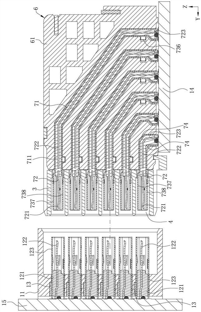
[0035] see Figure 1 to Figure 4 , which is an electrical connector combination 1 provided by an embodiment of the present invention, including an electrical connector 2 and a pair of mating connectors 10 docked with the electrical connector 2, the mating end 4 of the electrical connector 2 is along the The third direction Y is docked with one en...


PUM


Abstract

The invention discloses an electric connector, which comprises at least one electric module, and the electric module comprises an insulating body, a plurality of accommodating grooves being concavely arranged from a first side of the insulating body to a second side of the insulating body; a plurality of terminal assemblies, respectively accommodated in the corresponding accommodating grooves, each terminal assembly comprising an insulating block, a pair of signal terminals fixed on the insulating block and a shielding shell covering the insulating block and the signal terminals, and each shielding shell being provided with a first shielding side surface exposed out of the first side; a shielding piece, provided with a plurality of first spokes and a plurality of second spokes, each first spoke being in mechanical contact with the plurality of shielding shells located on the same electric module, and the plurality of second spokes being correspondingly fixed with the plurality of shielding shells; and each second spoke is in contact with the first shielding side surface of the corresponding shielding shell, so that the plurality of shielding shells are mutually conducted with the shielding piece, and the high-frequency performance of the electric connector is improved.

Description

【Technical field】 [0001] The invention relates to an electrical connector, in particular to an electrical connector with high frequency performance. 【Background technique】 [0002] A backplane electrical connector is known, for example, Chinese patent CN201580014851.4, see the attached specification of this patent Figure 4 A to Figure 8 B, the electrical connector includes a plurality of modules 910 assembled into a two-dimensional array, each module 910 includes a pair of conductive elements 925, 935 configured to carry differential signals, a housing that holds a pair of conductive elements 925, 935 The body 918 and the shielding member 916 surrounding the conductive elements 925 , 935 , a plurality of the modules 910 are assembled with each other through the protrusion 912 and the recess 914 of the shielding member 916 . [0003] However, in this electrical connector, the plurality of modules 910 are only assembled together through the protrusion 912 and the recess 914...

Claims


Application Information

Patent Timeline
Patent Type & Authority Applications(China)
IPC IPC(8): H01R13/42H01R13/6585H01R13/6581H01R13/6461H01R13/652
CPCH01R13/42H01R13/6585H01R13/6581H01R13/6461H01R13/652
Inventor 何志立
Owner 中山得意电子有限公司
Why Eureka
Try Eureka