Robot path precision compensation method and system
A precision compensation and robot technology, applied in the field of robots, can solve the problems of control bandwidth limitation, error compensation hysteresis, and difficulty in compensating for deformation, and achieve the effect of compensating for hysteresis and improving trajectory accuracy.
- Summary
- Abstract
- Description
- Claims
- Application Information
AI Technical Summary
Problems solved by technology
Method used
Image
Examples
Embodiment 1
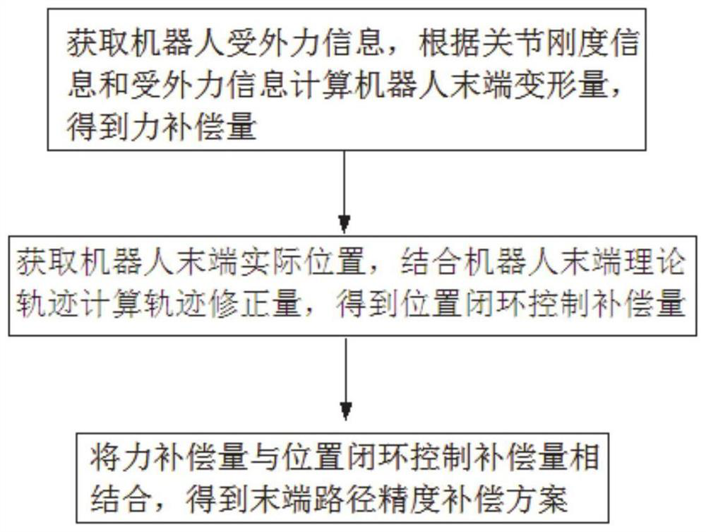
[0042] This embodiment provides a robot path accuracy compensation method, such as figure 1 shown, including:
[0043] Obtain the external force information of the robot, calculate the deformation of the robot end according to the joint stiffness information, joint angle information and external force information, and obtain the force compensation amount;
[0044] Obtain the actual position of the robot end, calculate the trajectory correction amount combined with the theoretical trajectory of the robot end, and obtain the position closed-loop control compensation amount;
[0045] Combining the force compensation part with the position closed-loop control compensation part, the end path accuracy compensation scheme is obtained, and the robot is controlled to complete the end accuracy compensation.
[0046] The purpose of this embodiment is to reduce the error caused by the internal parameters and external environmental factors of the robot, improve the end position accuracy o...
Embodiment 2
[0099] In order to verify the effectiveness of Embodiment 1, it is first necessary to analyze the uncompensated trajectory accuracy of the robot itself. The test trajectory selected in this embodiment (wherein, test trajectory=theoretical trajectory=preset trajectory=desired trajectory=experimental trajectory) is as follows: Figure 7 The coordinate values of the corresponding points are shown in Table 1. Wherein, the starting point is P10, and the end point is P36.
[0100] Table 1 Corresponding coordinate values of the experimental trajectory
[0101]
[0102]When the robot runs for 25 seconds according to the test track, the robot moves to the position P12. At this time, a sudden change load of 200N is applied to the end of the robot, and the load direction is along the Z-axis direction under the robot base frame. Since this embodiment mainly uses the Z-direction load, the tracking accuracy in the Z-direction is selected for verification.
[0103] Figure 8 is the...
Embodiment 3
[0112] This embodiment provides a robot path accuracy compensation system, including:
[0113] The force compensation amount calculation module is used to obtain the external force information of the robot, calculate the deformation amount of the robot end according to the joint stiffness information and the external force information, and obtain the force compensation amount;
[0114] The position closed-loop control compensation amount calculation module is used to obtain the actual position of the robot end, and calculate the trajectory correction amount combined with the robot end theoretical trajectory to obtain the position closed-loop control compensation amount;
[0115] The path accuracy compensation control module is used to combine the force compensation amount with the position closed-loop control compensation amount to obtain the end path accuracy compensation scheme.
PUM
 Abstract
Description
Claims
Application Information
 - R&D Engineer
- R&D Manager
- IP Professional
- Industry Leading Data Capabilities
- Powerful AI technology
- Patent DNA Extraction
Browse by: Latest US Patents, China's latest patents, Technical Efficacy Thesaurus, Application Domain, Technology Topic, Popular Technical Reports.
© 2024 PatSnap. All rights reserved.Legal|Privacy policy|Modern Slavery Act Transparency Statement|Sitemap|About US| Contact US: help@patsnap.com


