Underwater frequency transmission method and system based on active phase compensation
A frequency transfer, active phase technology, applied in transmission systems, optical transmission systems, electromagnetic wave transmission systems, etc., can solve the problems of complex structure of the transmitting end, limit the resolution of phase compensation, cost and increase in occupied space, etc., to achieve simple structure, Reduced complexity and low cost
- Summary
- Abstract
- Description
- Claims
- Application Information
AI Technical Summary
Problems solved by technology
Method used
Image


Examples
Embodiment 1
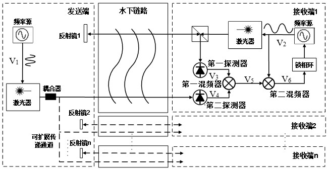
[0047] Underwater frequency transmission method based on active phase compensation, such as figure 1 As shown, including the following steps:
[0048] Step S100: The frequency source transmission frequency signal V is transmitted. 1 After the underwater link, the receiving end is transmitted to the receiving end, and the detection unit of the receiving end detects the frequency signal V. 4 ;
[0049] Step S200: The frequency source transmission frequency signal V is transmitted. 2 After the underwater link reaches the transmitting end, and after the reflection of the mirror of the transmitting end, it is again returned to the receiving end through the underwater link, and the detection portion of the receiving end is detected after the spatial link is separated. 3 ;
[0050] Step S300: Put the frequency signal V 3 With frequency signal V 4 Perform frequency mixing and filter out of the low frequency signal V 5 , Turn the frequency signal V 5 With frequency signal V 2 Get a near DC...
Embodiment 2
[0053] This embodiment is optimized on the basis of the first embodiment, the frequency source of the receiving end in the step S200 transmits frequency signal V. 2 After the polarization beam splitter, the modulated beam reaches the transmitting end through the underwater link and returns the polarization beam splitter of the receiving end after the reflection of the mirror, and then detects the frequency signal V. 3 .
[0054] Further, frequency signal V 1 Expressed as:
[0055]
[0056] Where f 1 Is the frequency of the sender, It is the initial phase of the sender;
[0057] Frequency signal V 2 Expressed as:
[0058]
[0059] Where f 2 Is the frequency of the receiving end, Is the initial phase shift of the receiving end;
[0060] Frequency signal V 3 Expressed as:
[0061]
[0062] in Is frequency signal V 2 Due to the phase fluctuation caused by the underwater link;
[0063] Frequency signal V 4 Expressed as:
[0064]
[0065] in Is frequency signal V 1 Due to th...
Embodiment 3
[0075] This embodiment is optimized on the basis of Example 1 or 2, such as figure 1 As shown, the receiving end is provided with several extensions, the transmitting passage including a mirror and a laser output channel; the frequency signal V transmitted by the transmitting end 1 The detection unit of the receiving end is transmitted to the receiving end and the frequency signal V is transmitted to the receiving end. 4 .
[0076] The technical solution proposed by the present invention supports frequency transfer simultaneously for multiple accept sites, solving problems that are difficult to perform frequencies to multiple reception sites simultaneously to multiple reception sites, such as star frequencies The transfer network is of great significance.
[0077] The other portions of the present embodiment are the same as those of the above-described Embodiment 1 or 2, so it will not be described again.
PUM
 Abstract
Description
Claims
Application Information
 - Generate Ideas
- Intellectual Property
- Life Sciences
- Materials
- Tech Scout
- Unparalleled Data Quality
- Higher Quality Content
- 60% Fewer Hallucinations
Browse by: Latest US Patents, China's latest patents, Technical Efficacy Thesaurus, Application Domain, Technology Topic, Popular Technical Reports.
© 2025 PatSnap. All rights reserved.Legal|Privacy policy|Modern Slavery Act Transparency Statement|Sitemap|About US| Contact US: help@patsnap.com