
Lens, backlight module and terminal equipment

A backlight module and lens technology, applied in optics, nonlinear optics, instruments, etc., can solve the problem of difficult miniaturization of reflective lenses, and achieve the effect of shortening the light mixing distance and realizing thinning.

Pending Publication Date: 2021-10-22
HUAWEI TECH CO LTD
View PDF16 Cites 0 Cited by
  • Summary
  • Abstract
  • Description
  • Claims
  • Application Information

AI Technical Summary

Problems solved by technology

[0004] The purpose of this application is to provide a lens, which aims to solve the technical problem that it is difficult to miniaturize the reflective lens in the prior art

Method used


Image

  • Lens, backlight module and terminal equipment
  • Lens, backlight module and terminal equipment
  • Lens, backlight module and terminal equipment

Examples


Embodiment Construction

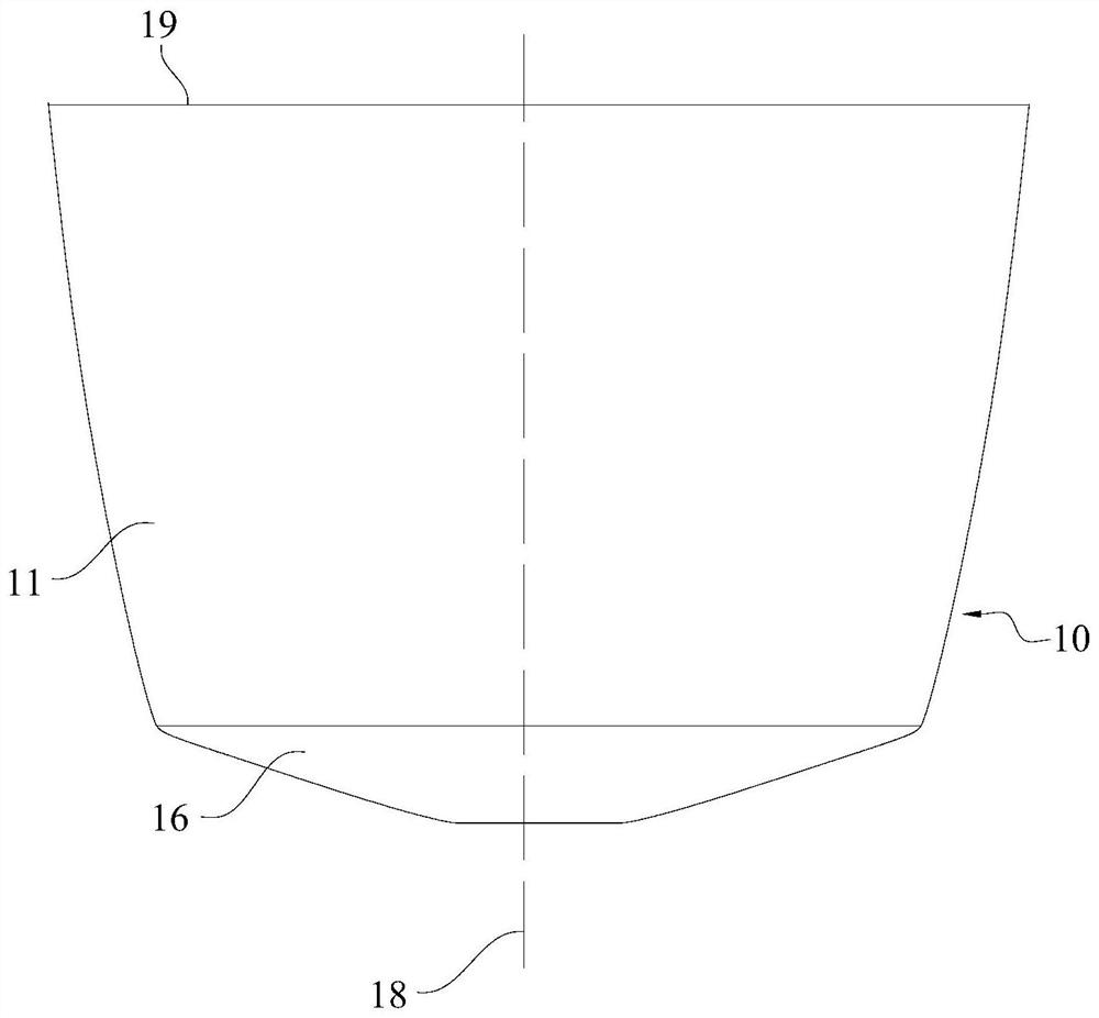
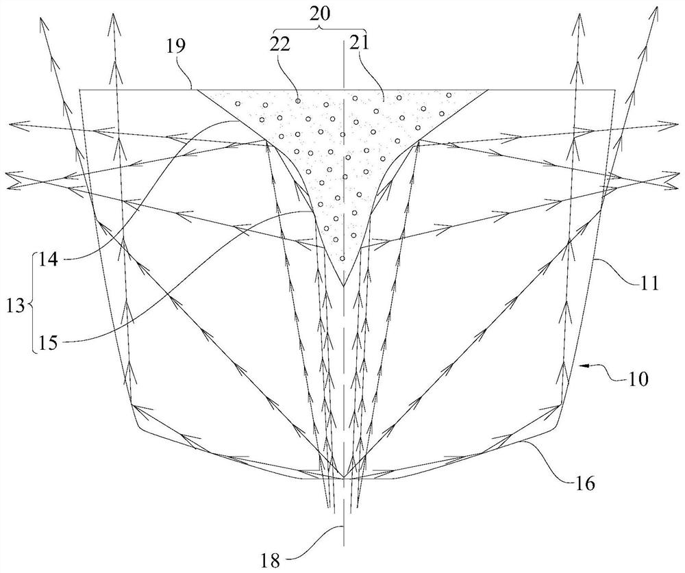
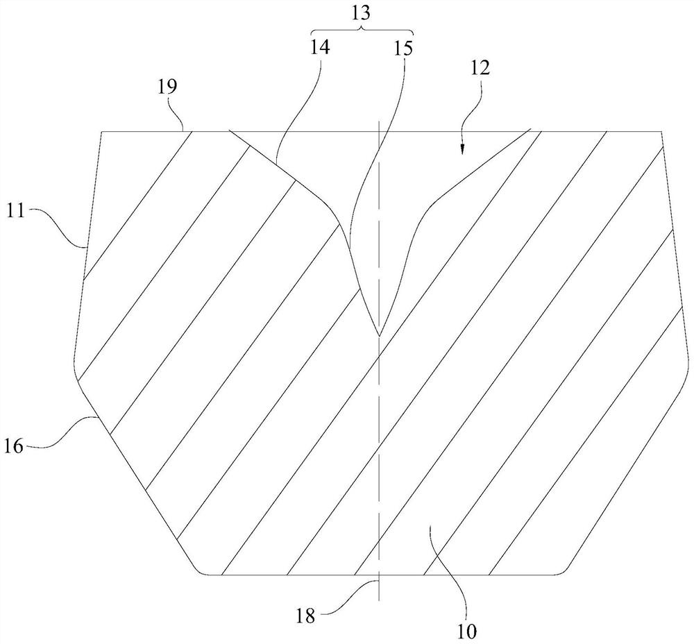
[0047]Embodiments of the present application are described in detail below, and examples of the embodiments are shown in the drawings, wherein the same or similar reference numerals denote the same or similar elements or elements having the same or similar functions throughout. Attached below by reference Figure 1-8 The described embodiments are exemplary and are intended to explain the application and not to be construed as limiting the application.

[0048] In the description of the present application, it should be understood that the terms "length", "width", "upper", "lower", "front", "rear", "left", "right", "vertical", The orientation or positional relationship indicated by "horizontal", "top", "bottom", "inner", "outer", etc. are based on the orientation or positional relationship shown in the drawings, and are only for the convenience of describing the application and simplifying the description, rather than Nothing to indicate or imply that a referenced device or el...


PUM

PropertyMeasurementUnit
angleaaaaaaaaaa
diameteraaaaaaaaaa
diameteraaaaaaaaaa

Abstract

The invention belongs to the technical field of lenses, and particularly relates to a lens, a backlight module and terminal equipment, the lens comprises a lens main body and a reflector, and the lens main body is provided with a reflection cavity for accommodating the reflector; a refracting surface which is at least used for refracting and reflecting light entering from the bottom of the lens main body to the position above the lens main body is formed on the outer wall of the peripheral side of the lens main body, and a first reflecting surface which is at least used for reflecting the light entering from the bottom of the lens main body to the peripheral side of the lens main body is formed on the cavity wall of the reflecting cavity of the reflecting body. The refracting surface is formed on the outer wall of the peripheral side of the lens main body, so that part of light incident from the bottom of the lens main body can be refracted to the area above the lens through the top surface of the lens and the refracting surface, the light emitting performance above the lens is improved, and the first reflecting surface enhances the light reflecting capacity of the peripheral side of the lens; therefore, the lens can obtain good light reflection performance without forming a large-area reflection surface, and the lens is easy to miniaturize.

Description

technical field [0001] The present application belongs to the technical field of lenses, and in particular relates to a lens, a backlight module and a terminal device. Background technique [0002] The lens is a key material in the backlight system of the liquid crystal display, which can diffuse the light generated by the LED light source to ensure the display brightness of the liquid crystal display. Existing lens types mainly include reflective lenses, which mainly reflect light through the upper surface of the lens and disperse it through the side surface. [0003] In the prior art, reflective lenses use the configuration of the lens itself to reflect light to its surrounding sides. One side of the reflective surface formed by the lens is made of lens material, and the other side is made of air. Due to the refraction of the air, If the rate is small, this will also lead to poor light reflection effect on the reflective surface. In order to pursue the reflection performa...

Claims


Application Information

Patent Timeline
Patent Type & Authority Applications(China)
IPC IPC(8): G02F1/13357
CPCG02F1/133606G02F1/133605
Inventor 熊充余俊逸段宝郭林浩
Owner HUAWEI TECH CO LTD
Learn More