
Direct-type macro LED package structure and direct-type macro LED light mixing device

A technology of LED packaging and light mixing device, applied in the field of backlight sources, can solve the problems of large light mixing distance, high discharge voltage, low luminous efficiency, etc., and achieve the effects of increasing light mixing efficiency, small light emitting angle, and uniform light emitting

Pending Publication Date: 2018-03-20
SHENZHEN REFOND OPTOELECTRONICS
View PDF7 Cites 9 Cited by
  • Summary
  • Abstract
  • Description
  • Claims
  • Application Information

AI Technical Summary

Problems solved by technology

[0002] With the continuous advancement of technology, the backlight technology of liquid crystal display has been continuously developed. The backlight of traditional liquid crystal display adopts cold cathode fluorescent lamp (CCFL), but due to the poor color reproduction ability, low luminous efficiency and high discharge voltage of CCFL backlight , Poor discharge characteristics at low temperature, long heating time to reach a stable gray level and other shortcomings, the backlight technology using LED backlight has been developed at present
[0003] LED backlights are mainly divided into two types: edge-lit and direct-lit. Traditional direct-lit backlights generally use multiple direct-lit LED lamp beads with independent lenses for secondary light distribution to achieve mixed light. The light mixing distance is large. As a result, the thickness of the entire display module is large, and it is difficult to meet the needs of the market

Method used


Image

  • Direct-type macro LED package structure and direct-type macro LED light mixing device
  • Direct-type macro LED package structure and direct-type macro LED light mixing device
  • Direct-type macro LED package structure and direct-type macro LED light mixing device

Examples


Embodiment Construction

[0027] The idea, specific structure and technical effects of the present invention will be clearly and completely described below in conjunction with the embodiments and accompanying drawings, so as to fully understand the purpose, features and effects of the present invention. Apparently, the described embodiments are only some of the embodiments of the present invention, rather than all of them. Based on the embodiments of the present invention, other embodiments obtained by those skilled in the art without creative efforts belong to The protection scope of the present invention. In addition, all the connection / connection relationships involved in the patent do not simply refer to the direct connection of components, but mean that a better connection structure can be formed by adding or reducing connection accessories according to specific implementation conditions. The various technical features in the present invention can be combined interactively on the premise of not co...


PUM


Abstract

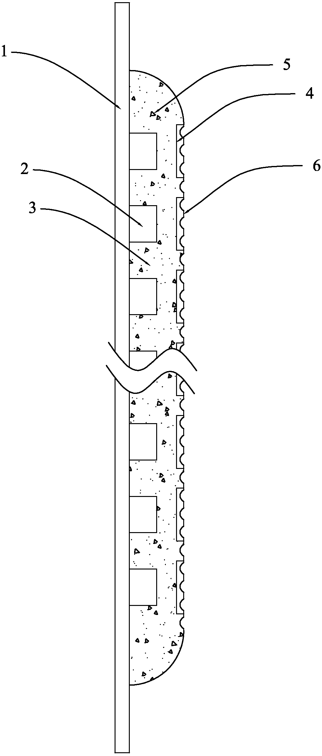
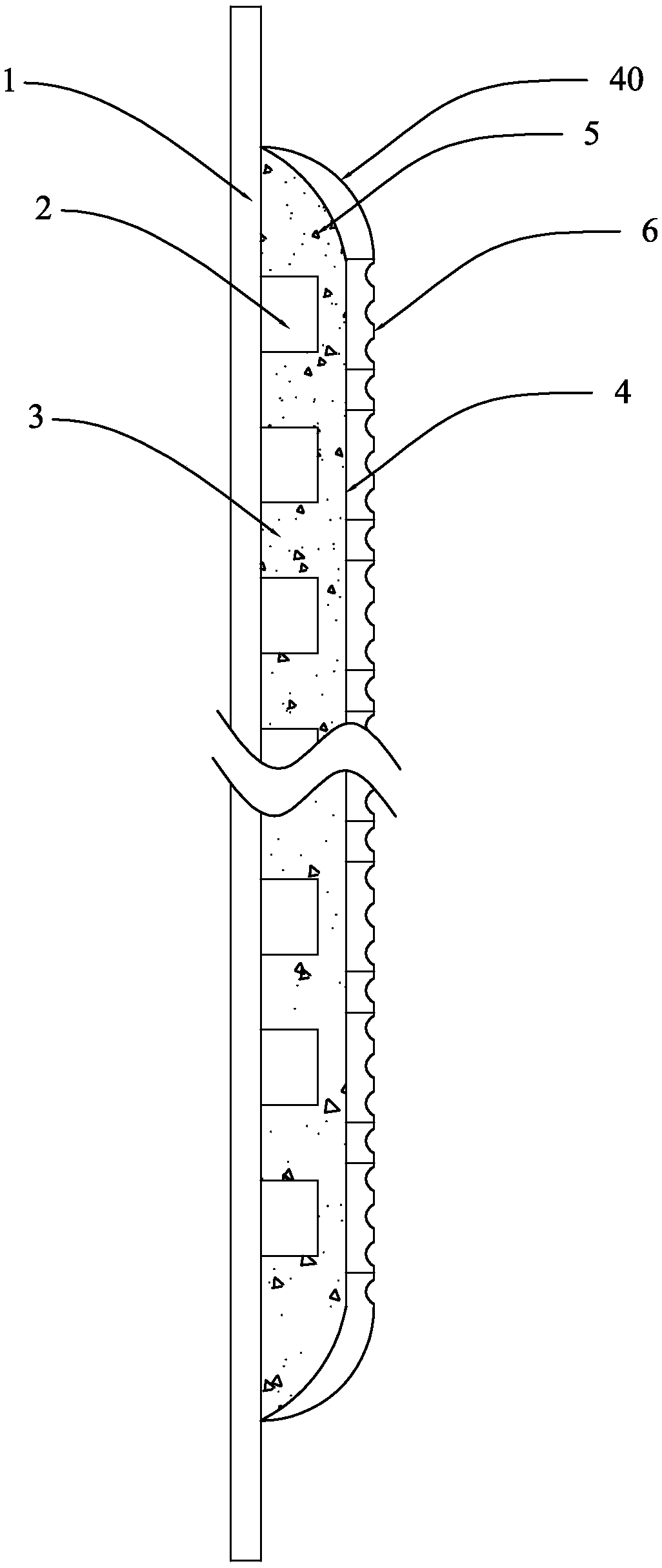
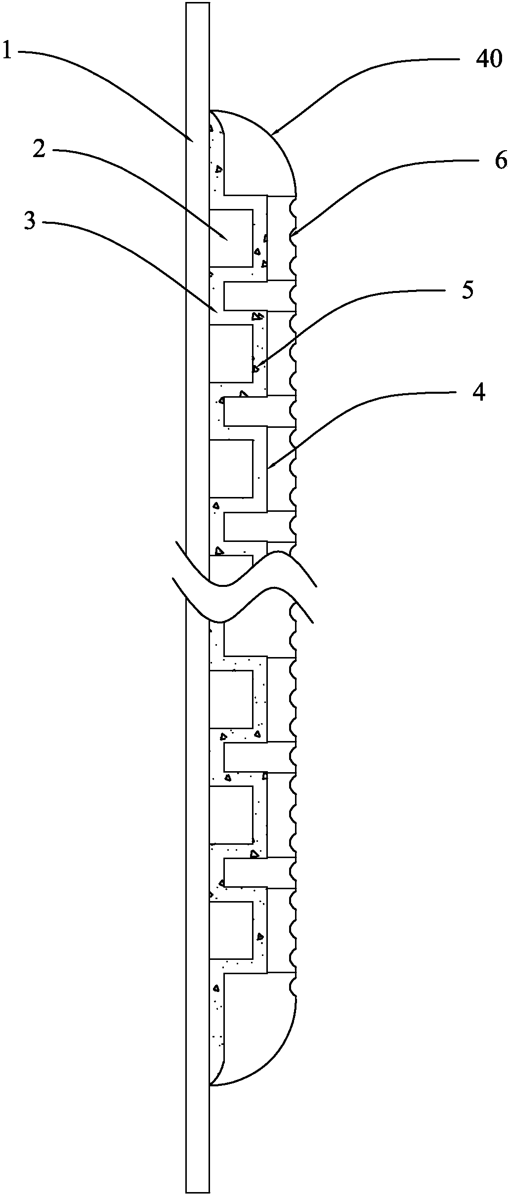
The invention discloses a direct-type macro LED package structure and a direct-type macro LED light mixing device and belongs to the technical field of backlight sources. The direct-type macro LED package structure comprises a PCB substrate and a plurality of LED chips fixedly arranged on the PCB substrate, wherein a light mixing layer is also fixedly arranged on the PCB substrate and coats the plurality of LED chips; the light mixing layer is filled with a fluorophor; a plurality of reflecting layers which correspond to the plurality of LED chips one by one are also fixedly arranged at the upper end of the light mixing layer; and the reflecting layers are arranged opposite to the corresponding LED chips. The direct-type macro LED light mixing device comprises the direct-type macro LED package structure, a lower diffusion film, a bright enhancement film, an upper diffusion film and a reflecting frame. According to the direct-type macro LED package structure, the light mixing distance can be significantly reduced and the thickness of the package structure is reduced. The direct-type macro LED light mixing device is smaller in thickness and more uniform in light emitting.

Description

technical field [0001] The invention belongs to the technical field of backlight sources, and in particular relates to a direct-down macro-pitch LED packaging structure and a direct-down macro-pitch LED light mixing device. Background technique [0002] With the continuous advancement of technology, the backlight technology of liquid crystal display has been continuously developed. The backlight of traditional liquid crystal display adopts cold cathode fluorescent lamp (CCFL), but due to the poor color reproduction ability, low luminous efficiency and high discharge voltage of CCFL backlight , Disadvantages such as poor discharge characteristics at low temperature and long time for heating to reach a stable gray level. At present, the backlight technology using LED backlight has been developed. [0003] LED backlights are mainly divided into two types: edge-lit and direct-lit. Traditional direct-lit backlights generally use multiple direct-lit LED lamp beads with independent...

Claims


Application Information

Patent Timeline
Patent Type & Authority Applications(China)
IPC IPC(8): H01L33/48H01L33/60
CPCH01L33/48H01L33/60
Inventor 张丽君
Owner SHENZHEN REFOND OPTOELECTRONICS
Learn More