
Elevator

A hoist and base technology, applied in the direction of conveyor objects, transportation and packaging, can solve the problem that the hoist cannot automatically sort the feeding efficiency, etc., and achieve the effect of improving the feeding efficiency and convenient removal.

Pending Publication Date: 2021-10-22
浙江云强智能装备有限公司
View PDF12 Cites 1 Cited by
  • Summary
  • Abstract
  • Description
  • Claims
  • Application Information

AI Technical Summary

Problems solved by technology

It solves the technical problem that the existing elevators cannot be automatically sorted and the feeding efficiency is low

Method used


Image

  • Elevator
  • Elevator
  • Elevator

Examples


Embodiment 1

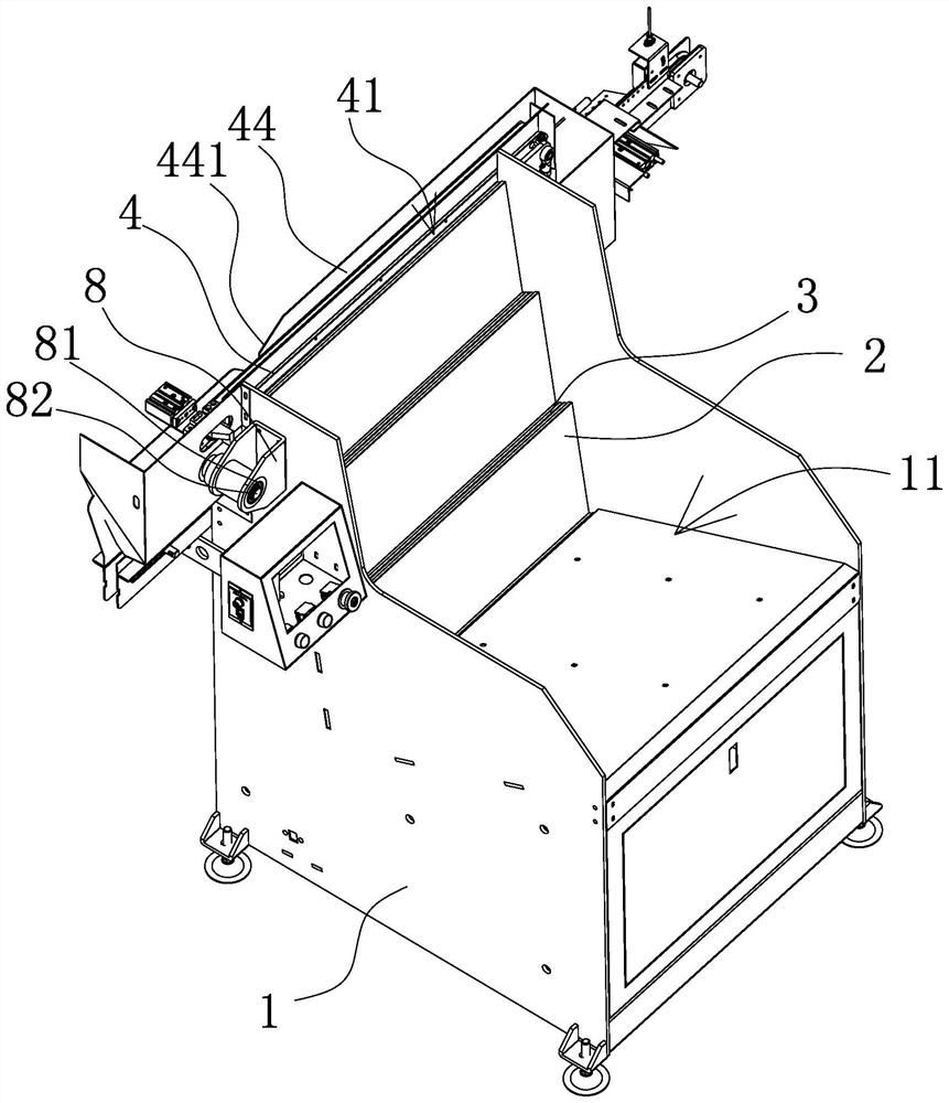
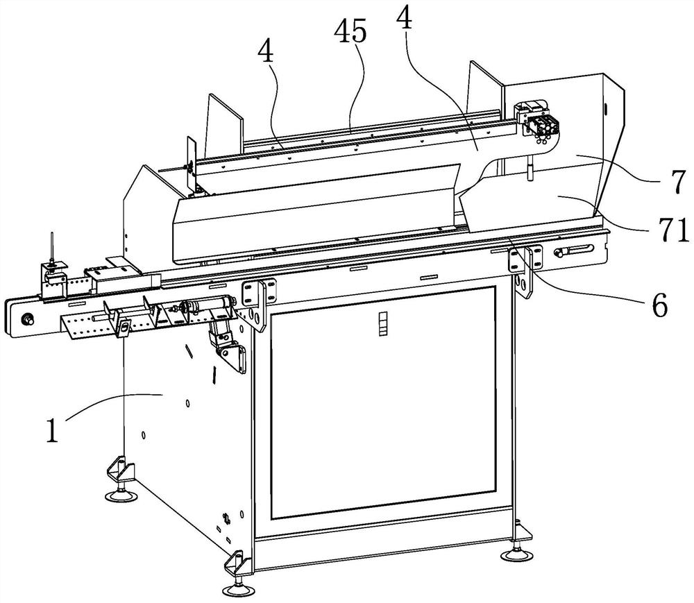
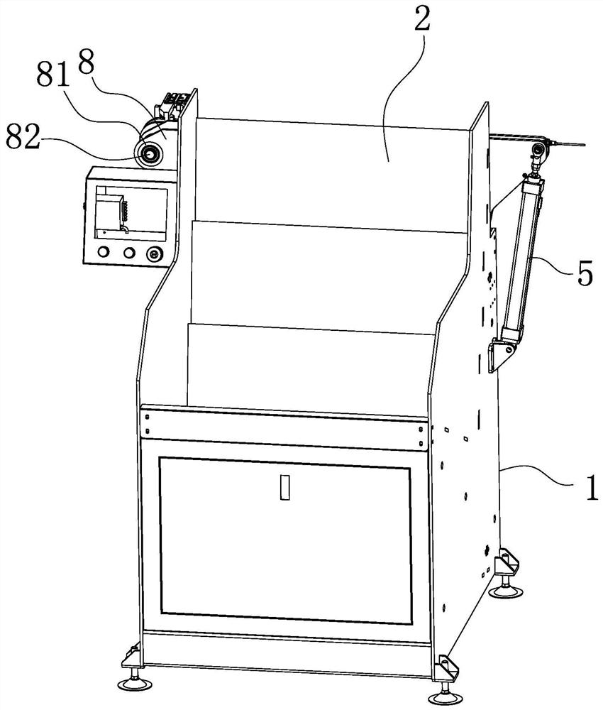
[0041] like Figure 1-8 One of the hoisting machines, including the housing 1 having the tank 11, and the housing 1 is located at the tank 11, which is provided with a stepped distribution, and the entire stepped base 2 is inclined distribution. of. The base 2 is composed of three step plates, and the bottom of the first step plate is located in the tank 11, and the movable plate 3 that can be up and down at the bottom of the tank 11, the highest bit movement of the movable plate 3 allows the movable plate 3 The upper end face is flushed to the upper end of the first step plate, and the minimum displacement distance of the movable plate 3 is flush with the bottom portion of the tank 11, so that when the material groove 11 is loaded into the workpiece, the movable plate 3 lifts and the first line plate. The flushing workpiece scrolls to the upper end of the first step plate under gravity action and stays there. There is also a movable plate 3 between the first step plate and the sec...

Embodiment 2

[0047] The structure and principle of the present embodiment are substantially identical, and the feed apparatus in the present embodiment includes a conveyor belt located on the guide rail 4, and the conveyor belt has two strips and respectively located on the left side plate 42 and the right side, respectively. On board 43. By setting the conveyor belt on the left side plate 42 and the right side plate 43 of the guide rail 3, the width of the conveyor belt is the same as the width of the left side plate 42 and the right side plate 43, the conveyor belt is in a state of scrolling, and the workpiece falls in the guide rail. 4 On the first conveyor belt, it can be used to transmit the work of the workpiece dropped on the guide rail 4, which effectively improves the feed efficiency of the lift.


PUM


Abstract

The invention provides an elevator, and belongs to the technical field of machining and manufacturing equipment. The problems that an existing elevator cannot achieve automatic sequencing and is low in feeding efficiency are solved. The elevator comprises a shell with a material groove, a step-shaped base is arranged in the material groove, a guide rail is arranged at the top of the base and distributed in the length direction of the top face, a through groove with an upward notch and penetrating through the two ends of the guide rail is formed in the guide rail in the length direction, the long edge of the lowest position of the base is close to the notch of the through groove, and one end of the guide rail is connected to the shell in a hinged mode, and the other end can be lifted when the guide rail rotates. When workpieces fall into the guide rail, the smaller-diameter ends of the workpieces can fall into the through groove, the larger-diameter ends of the workpieces can be clamped at the notch positions of the through groove, automatic sorting of the workpieces is achieved, the guide rail can rotate around a hinge point under the ejecting pressure of an air cylinder, the workpieces clamped on the guide rail can slide towards the lower side along with rotation of the guide rail, the workpieces can be conveniently taken down by people, and the feeding efficiency is further improved.

Description

Technical field [0001] The invention belongs to the technical field of processing manufacturing equipment, involving a hoist. Background technique [0002] The hoist is a machine that is currently used to raise transport materials in the market. There are many kinds of hoists, in which the parade hoist is widely used in the transport of round tube or cylindrical workpieces. The step hoist is mainly used to enhance the workpiece of the round tube, such as bolts, circular tubes, etc., the main working principle of the step-by-step hoist is to form a step-shaped base, and the entire susceptor is slightly The inclined, each step is inclined, and each step has a lifting block that can be up and down. When the workpiece is moving up and down, the workpiece level will be upgraded, the workpiece is Each tilt step is rolled to the lifting block at the step, and the lowest level of the stepped shape is provided in the tank, and the tank is tilted toward the step direction, and the cylindri...

Claims


Application Information

Patent Timeline
Patent Type & Authority Applications(China)
IPC IPC(8): B65G47/24
CPCB65G47/24
Inventor 韩方强蔡遂生赵亚衡秦亮
Owner 浙江云强智能装备有限公司
Learn More