Nozzle provided with anti-blocking device and used for injection molding machine

An injection molding machine and anti-blocking technology, which is applied in the field of injection molding machine nozzles, can solve problems such as delaying operations, easily affecting discharge, and poor use effects, and achieves the effects of preventing material blockage, improving stability, and improving scraping quality and efficiency

Inactive Publication Date: 2021-10-22
陈涛
View PDF1 Cites 0 Cited by
  • Summary
  • Abstract
  • Description
  • Claims
  • Application Information

AI Technical Summary

Problems solved by technology

At present, injection molding machines generally use nozzles to discharge materials, but the diameter of the nozzles is small, and it is easy to block during the process of extruding materials. The failure of the whole equipment requires large-scale repairs, which seriously delays the operation, and the materials that stay inside the shell for a long time are easy to harden and agglomerate, which brings more trouble to the maintenance work
[0003] In the publication number "CN109664465B" proposed "an injection molding machine nozzle anti-blocking device and its use method", the patent drives the first gear to rotate through the flow of materials, the first gear drives the driving gear to rotate, and the driving gear passes through the chain Drive the driven gear to rotate, and the driven gear drives the second gear to rotate to realize the anti-blocking of the nozzle, but because the transmission structures such as gears and chains are arranged in the shell, they will contact with the material, and the material remains on the transmission structure, not only It causes waste, and if the material is not treated cleanly, it is easy to harden and agglomerate, resulting in the problem of chain breakage, so that the swing frame cannot perform anti-blocking operations, and the use effect is poor. At the same time, the swing frame can only be set in the nozzle. The residual material remaining on the inner wall of the nozzle cannot be removed, and the residual material on the inner wall of the nozzle is likely to affect the discharge of subsequent materials, and the deblocking effect is poor. For this reason, we propose a nozzle for injection molding machines with an anti-blocking device

Method used


Image

  • Nozzle provided with anti-blocking device and used for injection molding machine
  • Nozzle provided with anti-blocking device and used for injection molding machine
  • Nozzle provided with anti-blocking device and used for injection molding machine

Examples


Embodiment 1

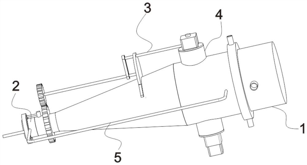
[0025] see Figure 1-5 , the present invention provides the nozzle for injection molding machine with anti-blocking device (the electrical components among the present invention are all connected with external power supply by wire), comprising,

[0026] Shell 1, the right section of the shell 1 is cylindrical, and the left section is truncated. The left side of the shell 1 is provided with a nozzle 2, which is fixed to the shell 1 through a connecting frame 5. The connecting frame 5 is U-shaped. The top of the shell 1 and the The right side of the bottom is fixedly inserted with a fixed pipe 4 connected to each other, and the shell 1 is also provided with structures such as a feed inlet and a cooling water ring. "Anti-blocking device and its method of use" have been disclosed, and will not be described in detail here;

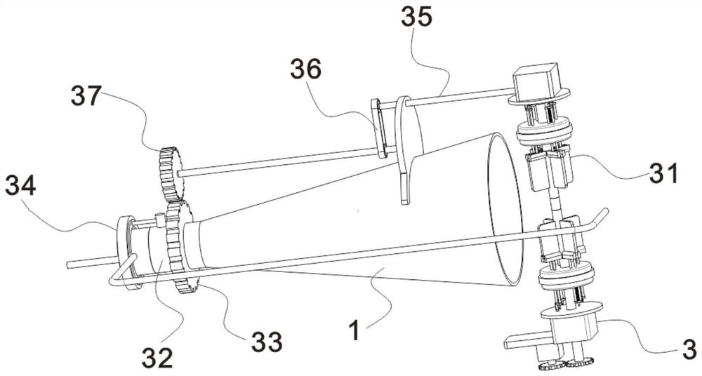
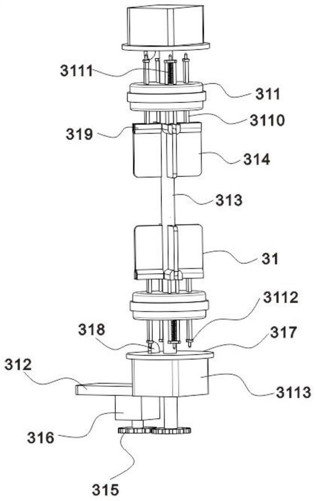
[0027] The anti-clogging part 3 includes a driving part 31 arranged in the fixed pipe 4. The left side of the housing 1 is provided with a connected follower ...

Embodiment 2

[0033] see Figure 4-5 , the scraping disturbing member 34 includes a hollow tube 341 fixedly inserted on the left side of the top of the follower ring 32, the hollow tube 341 rotates with the follower ring 32, the top and bottom of the hollow tube 341 are closed, and the hollow tube 341 is in a follower position. On the left side of the gear 33, the left side of the hollow tube 341 is fixedly inserted with a connected hollow assembly plate 345, the gas entering the hollow tube 341 can enter the hollow assembly plate 345, and the hollow assembly plate 345 is in the follower ring 32, hollow There is a groove on the top of the assembly plate 345, and a scraper 346 that fits the inner wall of the follower ring 32 and the inner wall of the nozzle 2 is movably inserted in the groove, and the bottom of the scraper 346 is fixed to the bottom of the groove by multiple sets of springs .

[0034] All the other structures are identical with embodiment 1

[0035] Compared with Embodimen...

Embodiment 3

[0037] see Figure 5 , the outer wall of the nozzle 2 is fixedly sleeved with an assembly ring 342, the assembly ring 342 does not rotate, and an annular cavity (not shown in the figure) is provided in the assembly ring 342, and an annular cavity communicating with the annular cavity is provided on the right side of the assembly ring 342. The ring mouth is provided with a rotating ring 344 through bearing rotation. The rotating ring 344 can rotate with the hollow pipe 341. The top of the left outer wall of the hollow pipe 341 is fixedly inserted with a connecting air pipe, and the other side of the connecting air pipe is fixedly inserted with a rotating ring. 344 and communicates with the annular cavity, so that the gas in the annular cavity can enter the hollow tube 341, the left side of the assembly ring 342 is fixedly inserted with a connecting hose 343 communicating with the annular cavity, and the other end of the connecting hose 343 is connected to the external gas supply...


PUM


Abstract

The invention discloses a nozzle provided with an anti-blocking device and used for an injection molding machine, and belongs to the technical field of injection molding machine nozzles. The nozzle comprises a shell and an anti-blocking piece; a nozzle body is arranged on the left side of the shell; the anti-blocking piece comprises a driving piece arranged in a fixed pipe, a follow-up ring communicating with the shell is rotationally arranged on the left side of the shell through a bearing, and the left side of the follow-up ring is rotationally connected with the nozzle body through a bearing. Flow of materials can drive a power plate to enable a driving column to rotate, so that a follow-up gear is driven through a transmission rod, a chain wheel transmission set, an auxiliary rod and a transmission gear to enable the follow-up ring to rotate, the nozzle is treated through a scraping disturbance part, a transmission structure in the mode is not affected by the internal flowing materials, and the long-term stable blockage removal operation quality is ensured.

Description

technical field [0001] The invention relates to the technical field of injection molding machine nozzles, in particular to an injection molding machine nozzle with an anti-blocking device. Background technique [0002] Injection molding machine is also known as injection molding machine or injection machine. At present, injection molding machines generally use nozzles to discharge materials, but the diameter of the nozzles is small, and it is easy to block during the process of extruding materials. The failure of the whole equipment requires large-scale maintenance, which seriously delays the operation, and the materials that stay inside the shell for a long time are easy to harden and agglomerate, which brings more trouble to the maintenance work. [0003] In the publication number "CN109664465B" proposed "an injection molding machine nozzle anti-blocking device and its use method", the patent drives the first gear to rotate through the flow of materials, the first gear dr...

Claims


Application Information

Patent Timeline
Patent Type & Authority Applications(China)
IPC IPC(8): B29C45/20B29C45/74
CPCB29C45/20B29C45/74
Inventor 陈涛
Owner 陈涛
Why Eureka
Try Eureka