
LED constant-current driving circuit and controller

A constant current drive and circuit technology, applied in the direction of electrical components, etc., can solve the problems of LED current overshoot, and achieve the effect of avoiding overshoot, reducing LED current, and increasing equivalent impedance

Pending Publication Date: 2021-10-19
MAXIC TECHNOLOGY CORPORATION
View PDF0 Cites 0 Cited by
  • Summary
  • Abstract
  • Description
  • Claims
  • Application Information

AI Technical Summary

Problems solved by technology

[0003] Based on this, the technical problem to be solved by the present invention is to overcome the defect that the LED current will overshoot when the input voltage of the LED drive circuit using a hysteresis switch controller in the prior art is close to the LED voltage, thereby providing a LED constant current drive circuit and controller

Method used


Image

  • LED constant-current driving circuit and controller
  • LED constant-current driving circuit and controller
  • LED constant-current driving circuit and controller

Examples


Embodiment Construction

[0028] The technical solutions of the present invention will be described below in conjunction with the drawings, which is apparent from the accompanying drawings. Based on the embodiments of the present invention, all other embodiments obtained by those of ordinary skill in the art are in the range of the present invention without making creative labor premise.

[0029] In the description of the present invention, it is to be noted that the terms "center", "upper", "lower", "left", "right", "vertical", "horizontal", "within", "outside", etc. The orientation or positional relationship indicated is based on the orientation or positional relationship shown in the drawings, is meant to facilitate the description of the present invention and simplified description, rather than indicating or implying that the device or component must have a specific orientation. Construct and operation, so it is not understood to be the limitation of the invention. Moreover, the term "first", "second",...


PUM


Abstract

The invention provides an LED constant-current driving circuit and a controller. The LED constant-current driving circuit comprises a first switching circuit, a constant-on detection circuit, a control circuit and a second switching circuit, wherein the first end of the first switching circuit is externally connected with a PWM driving signal, and the second end of the first switching circuit is connected with a target LED load; the input end of the constant-on detection circuit is connected with the first end of the first switching circuit and the first input end of the control circuit, and the output end is connected with the second input end of the control circuit; the output end of the control circuit is connected with the first end of the second switching circuit, the second end of the second switching circuit is connected with the target LED load, and the control circuit is used for generating a control signal according to the detection result and the PWM driving signal so as to control the working state of the second switching circuit. The second switching circuit is controlled to be switched off, the equivalent impedance of the circuit is increased, the LED current is reduced, and the purpose of preventing the LED current from generating overshoot is achieved.

Description

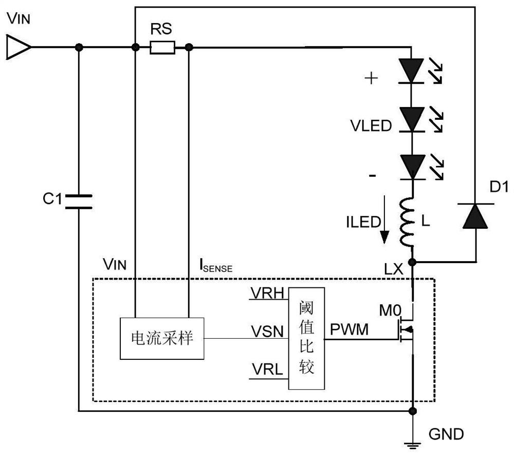
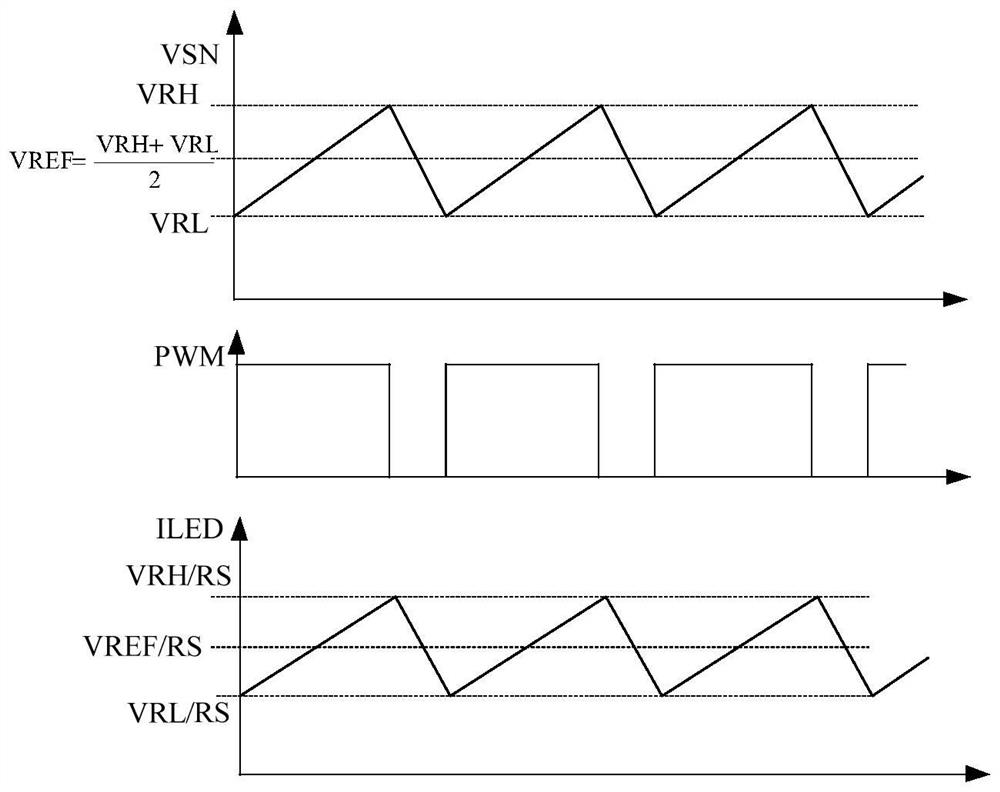
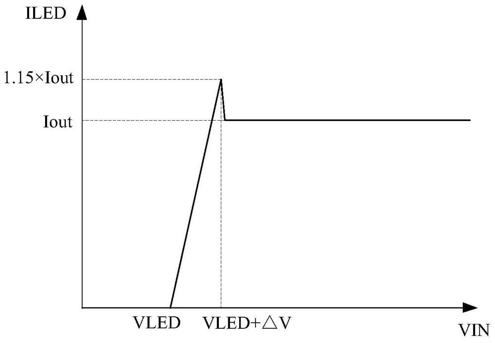
Technical field [0001] The present invention relates to the field of electronic circuit technology, and more particularly to an LED constant current drive circuit and a controller. Background technique [0002] The LED is rapidly developed in the lighting industry due to the advantages of low energy consumption, long life, low pollution. With the popularity of LED light sources, the LED constant current drive control has been put forward higher requirements, requiring higher constant current accuracy and decrease in LED driving cost. In the prior art, the hysteresis switch controller is usually implemented, and the advantage is that the constant current accuracy is high, the chip cost is low, and the drive current is large. However, when the input voltage is close to the LED voltage, the hysteresis switch controller will be in a constant state, resulting in approximately 15% of the LED current at this time, and current overshoot, which is used for battery powered applications, es...

Claims


Application Information

Patent Timeline
Patent Type & Authority Applications(China)
IPC IPC(8): H05B45/345H05B45/325H05B45/50
CPCH05B45/345H05B45/325H05B45/50
Inventor 牟在鑫
Owner MAXIC TECHNOLOGY CORPORATION
Learn More