


Quick Research
Generate reliable direction feasibility study reports for your R&D in just a few steps.

Technical Q&A
Discover and master advanced knowledge NOW. Basics, ideas, possibilities, all at once.

Find Solutions
As an expert in R&D theories, this can generate solutions to your technical problems instantly.

Evaluate Feasibility
Analyze your overall solution with one click, know your potential R&D risks in advance.

Monitor Landscape
Get weekly tech updates, stay abreast of the latest tech innovations and key insights.
System and method for measuring magnetic refraction effect of optical fiber
A measurement system and magnetostrictive technology, which is applied in the use of magneto-optical equipment for magnetic field measurement, magnetic field size/direction, etc., can solve the problems of complex sensing structure, high system maintenance cost, difficult sensor fabrication, etc., and achieve high sensitivity , Simple structure, avoid the effect of complex coating process
- Summary
- Abstract
- Description
- Claims
- Application Information
AI Technical Summary
Problems solved by technology
Method used
Image

Examples
Embodiment 1
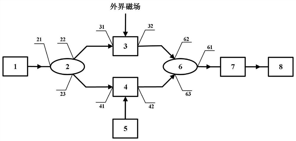
[0042] In this example, see figure 1 , a fiber optic magnetoresistive effect measurement system, including a laser 1, a coupler A 2, a sensing fiber 3, a reference fiber 4, a carrier generator 5, a coupler B 6, a photodetector 7, and a data acquisition and processing module 8;
[0043] The output port of the laser 1 is connected to the first port 21 of the coupler A 2, the second port 22 of the coupler A 2 is connected to the first port 31 of the sensing fiber 3, and the third port 23 of the coupler A 2 Connect with the first port 41 of the reference fiber 4; the second port 32 of the sensing fiber 3 is connected with the second port 62 of the coupler B 6, and the second port 42 of the reference fiber 4 is connected with the second port 62 of the coupler B 6 Three ports 63 are connected; the first port 61 of the coupler second 6 is connected with the input port of the photodetector 7; the input port of the data collection and processing module 8 is connected with the output p...
Embodiment 2
[0049] This embodiment is basically the same as Embodiment 1, especially in that:
[0050] In this example, see figure 1 , coupler A 2, sensing fiber 3, reference fiber 4, and coupler B 6 are connected to form a Mach-Zehnder fiber interferometer, sensing fiber 3 constitutes the sensing arm of the Mach-Zehnder fiber interferometer, and reference fiber 4 constitutes the Mach-Zehnder fiber interferometer -The reference arm of the Zehnder fiber interferometer, the first port 21 of the coupler A 2 is the optical input port of the Mach-Zehnder fiber interferometer, and the first port 61 of the coupler B 6 is the light output port of the Mach-Zehnder fiber interferometer .
[0051] In this example, see figure 1 , the system is based on the magnetorefractive effect of the sensing fiber 3, the refractive index of the sensing fiber 3 is modulated by an external magnetic field, which causes the optical path difference of the two optical signals in the sensing fiber 3 and the reference ...
Embodiment 3
[0055] This embodiment is basically the same as the above-mentioned embodiment, and the special features are:
[0056] In this example, see figure 1 and figure 2 , a system and method for measuring optical fiber magnetoresistive effect according to claim 1, comprising the following steps:
[0057] a. The optical signal output by the laser 1 is divided into two beams of light transmitted by the sensing fiber 3 and the reference fiber 4 through the coupler A 2, and the two beams of light interfere at the coupler B 6, and the intensity of the interference light signal is detected by the photodetector 7 detection;
[0058] b. During DC magnetic field measurement, a DC magnetic field is applied on the sensing fiber 3, and the magnetic field changes the refractive index of the sensing fiber 3, causing the optical path difference between the sensing fiber 3 and the optical signal in the reference fiber 4 to change, changing the coupler B 6 The intensity of the output interference...
PUM
 Abstract
Description
Claims
Application Information
 - R&D Engineer
- R&D Manager
- IP Professional
- Industry Leading Data Capabilities
- Powerful AI technology
- Patent DNA Extraction
Browse by: Latest US Patents, China's latest patents, Technical Efficacy Thesaurus, Application Domain, Technology Topic, Popular Technical Reports.
© 2024 PatSnap. All rights reserved.Legal|Privacy policy|Modern Slavery Act Transparency Statement|Sitemap|About US| Contact US: help@patsnap.com