Clutch quick release mechanism and linear actuator
A technology of linear actuator and release mechanism, which is applied in the direction of mechanical equipment, transmission, gear vibration/noise attenuation, etc. It can solve the problems that the release mechanism cannot be released smoothly, achieve low noise, overcome wear and deformation, and release smoothly Effect
- Summary
- Abstract
- Description
- Claims
- Application Information
AI Technical Summary
Problems solved by technology
Method used
Image

Examples
Embodiment 1)
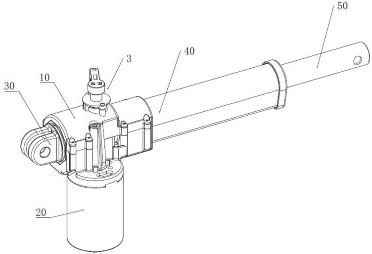
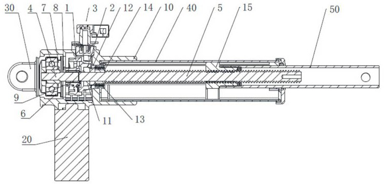
[0032] See figure 1 , figure 2 , image 3 , Figure 4 , the present invention provides a clutch quick release mechanism, including a screw, a worm gear 1, a clutch 2 that is in transmission cooperation with the worm gear 1, and a controller 3 acting on the worm gear 1, the screw includes a screw head 4 and a screw main body 5, The worm gear 1 is sleeved on the screw head 4 and can be displaced axially along the screw head 4 , the clutch 2 is sleeved on the screw main body 5 , and the controller 3 is used to drive the worm gear 1 to disconnect from the clutch 2 .
[0033] This embodiment is a basic embodiment of a clutch quick release mechanism. The axis line of the screw head 4 is the same as the axis line of the screw body 5, but there is a gap between the screw head 4 and the screw body 5. not in contact. The clutch 2 can be connected to the main body of the screw rod 5 in an interference fit manner. The screw head 4 can be made of a material with a low coefficient of ...
Embodiment 2)
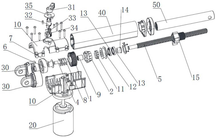
[0037] See figure 1 , figure 2 , image 3 , Figure 4 The difference between this embodiment and Embodiment 1 is that the controller 3 has a control switch 31, a connecting portion 32, a first elastic member 33, and a toggle switch 34, and the control switch 31 and the toggle switch 34 are located at the connecting portion 32 respectively. At both ends, the first elastic member 33 is located between the connecting portion 32 and the toggle switch 34 . When the control switch 31 rotates, it drives the connecting portion 32 to rotate, and the connecting portion 32 drives the toggle switch 34 to rotate, and the toggle switch 34 toggles the worm gear 1 away from the clutch 2 for release. The first elastic member 33 may be, but not limited to, elastic members such as torsion springs, and the first elastic member 33 provides a restoring force to return to the original position after the toggle switch 34 is toggled.
Embodiment 3)
[0039] See figure 2 , image 3The difference between this embodiment and Embodiment 1 is that the screw head 4 is fixedly connected with a support 6 , and a second elastic member 8 is provided between the worm wheel 1 and the support 6 . The support 6 may be, but not limited to, a ball bearing. During normal operation, the second elastic member 8 provides an axial force to press the worm gear 1. The second elastic member 8 can be but not limited to compression springs, wave springs and other elastic components. After the controller 3 realizes the effective release, the second elastic member 8 can make the worm gear 1 return to its original position, continue to cooperate with the clutch 2 to work or wait for the next release.
[0040] The screw head 4 and the support member 6 can also be an integral structure, and the screw head 4 and the support member 6 are used for interference fit. Alternatively, as a structural improvement and optimization, a first sleeve 7 may be pro...
PUM
 Abstract
Description
Claims
Application Information
 - R&D
- Intellectual Property
- Life Sciences
- Materials
- Tech Scout
- Unparalleled Data Quality
- Higher Quality Content
- 60% Fewer Hallucinations
Browse by: Latest US Patents, China's latest patents, Technical Efficacy Thesaurus, Application Domain, Technology Topic, Popular Technical Reports.
© 2025 PatSnap. All rights reserved.Legal|Privacy policy|Modern Slavery Act Transparency Statement|Sitemap|About US| Contact US: help@patsnap.com