An electric vehicle power acceleration control system
An acceleration control, electric vehicle technology, applied in electric vehicles, electric components, control drives, etc., can solve the problems of high motor failure rate, braking failure, poor reliability of electric vehicles, etc., and achieve low motor failure rate and reliable braking. , The effect of high safety
- Summary
- Abstract
- Description
- Claims
- Application Information
AI Technical Summary
Problems solved by technology
Method used
Image
Examples
Embodiment 1
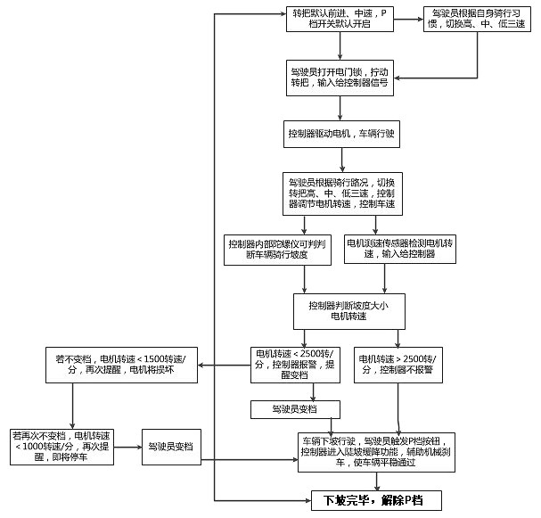
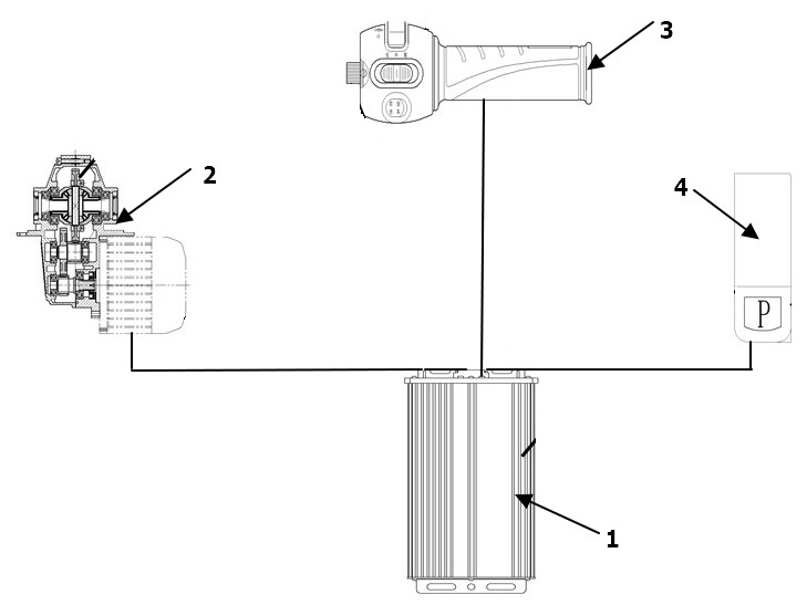
[0079] like figure 1 and figure 2 As shown, the electric vehicle power acceleration control system of the present application includes a motor 1, a gearbox 2, a handlebar 3 and a P gear switch 4; the motor 1 includes a motor speed sensor and a controller.
[0080] The motor speed sensor signal is output to the controller, and the controller constantly detects the motor speed. When the motor 1 speed is lower than 2500 rpm, the controller outputs an alarm to prompt the driver to switch to the mechanical gear low gear;
[0081] Preferably, the structure of the motor 1 is a magnetic steel embedded motor, which is more suitable for field weakening control, has the characteristics of large torque, high magnetic field strength, sustainable high temperature operation, and ensures stable power output of the system;
[0082] Preferably, a gyroscope is positioned inside the controller, and the controller can measure the slope when the vehicle is climbing, accurately output the control ...
Embodiment 2
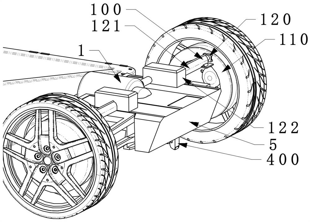
[0095] In order to further reduce the probability of electric vehicle brake failure and improve the reliability of the electric vehicle; the embodiment of the present application adds an auxiliary brake assembly 100 on the basis of the above-mentioned embodiment, and the auxiliary brake assembly 100 is used in conjunction with a mechanical brake to reduce brake failure. probability.
[0096] Specifically: the electric vehicle power acceleration control system further includes an auxiliary brake assembly 100;
[0097] The auxiliary brake assembly 100 is as follows image 3 and Figure 5 As shown, including annular brake plate 110 and auxiliary brake module 120;
[0098] like Figure 5 and Image 6 As shown, the main body of the annular brake plate 110 is annular, fixed on the wheel of the vehicle, and rotates synchronously with the wheel of the vehicle. The braking module 120 cooperates to increase the braking effect;
[0099] The auxiliary brake module 120 is as follows ...
Embodiment 3
[0117] In order to further improve the practicability of the present application and the reliability of the electric vehicle, the embodiment of the present application adds an auxiliary outrigger assembly 400 on the basis of the above-mentioned embodiment; when the vehicle is on a slope, the controller controls the auxiliary outrigger assembly 400 Running to avoid vehicle slippage;
[0118] further, as Figure 4 , Figure 15 and Figure 16 As shown, the auxiliary outrigger assembly 400 is positioned at the bottom of the vehicle frame 5, and includes an outrigger body 410, an outrigger positioning assembly 420 and an outrigger driving assembly 430; the outrigger positioning assembly 420 serves as a fixed support The function of the leg main body 410; the outrigger driving assembly 430 is used to drive the outrigger main body 410 to run.
[0119] preferably, as Figure 15 As shown, the main body 410 of the outrigger is a telescopic outrigger 411,
[0120] The outrigger posi...
PUM
 Abstract
Description
Claims
Application Information
 - R&D
- Intellectual Property
- Life Sciences
- Materials
- Tech Scout
- Unparalleled Data Quality
- Higher Quality Content
- 60% Fewer Hallucinations
Browse by: Latest US Patents, China's latest patents, Technical Efficacy Thesaurus, Application Domain, Technology Topic, Popular Technical Reports.
© 2025 PatSnap. All rights reserved.Legal|Privacy policy|Modern Slavery Act Transparency Statement|Sitemap|About US| Contact US: help@patsnap.com


