
Stainless steel wire strength detection equipment based on elasticity testing mechanism

A technique of elasticity testing and strength testing, applied in the direction of applying stable tension/pressure to test material strength, strength characteristics, measuring devices, etc., can solve problems such as unfavorable use, uneven force, inability to adjust, etc., to extend service life , Avoid high temperature, improve the effect of stability

Pending Publication Date: 2021-10-15
安徽珂洁日用品有限公司
View PDF0 Cites 1 Cited by
  • Summary
  • Abstract
  • Description
  • Claims
  • Application Information

AI Technical Summary

Problems solved by technology

[0002] Stainless steel wire is one of the four types of stainless steel plates, tubes, shapes, and wires. It is a reprocessed product made of hot-rolled wire rods by cold drawing. Among them, stainless steel wires are produced into spring stainless steel wires, which have high strength and low cost. , has a long service life and is widely used in production, but the strength of spring stainless steel wire needs to be tested during production to test the elasticity of spring stainless steel wire to ensure that it can be used under a certain range of strength without damage. At present, testing equipment needs to be used when using The spring stainless steel wire is limited to avoid the impact of the spring dumping on the detection effect, but the current detection equipment cannot adjust the limit range according to the spring stainless steel wire of different sizes or heights, and the applicability is lacking, resulting in some spring stainless steel wires being squeezed downward. During pressure testing, the force is uneven, which affects the test results and is not conducive to subsequent use. In view of this, we propose a stainless steel wire strength testing equipment based on an elastic testing mechanism

Method used


Image

  • Stainless steel wire strength detection equipment based on elasticity testing mechanism
  • Stainless steel wire strength detection equipment based on elasticity testing mechanism
  • Stainless steel wire strength detection equipment based on elasticity testing mechanism

Examples


Embodiment 1

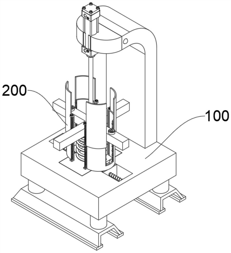
[0038] see Figure 1-Figure 4 As shown, the present embodiment provides a stainless steel wire strength detection device based on an elastic testing mechanism, including at least:

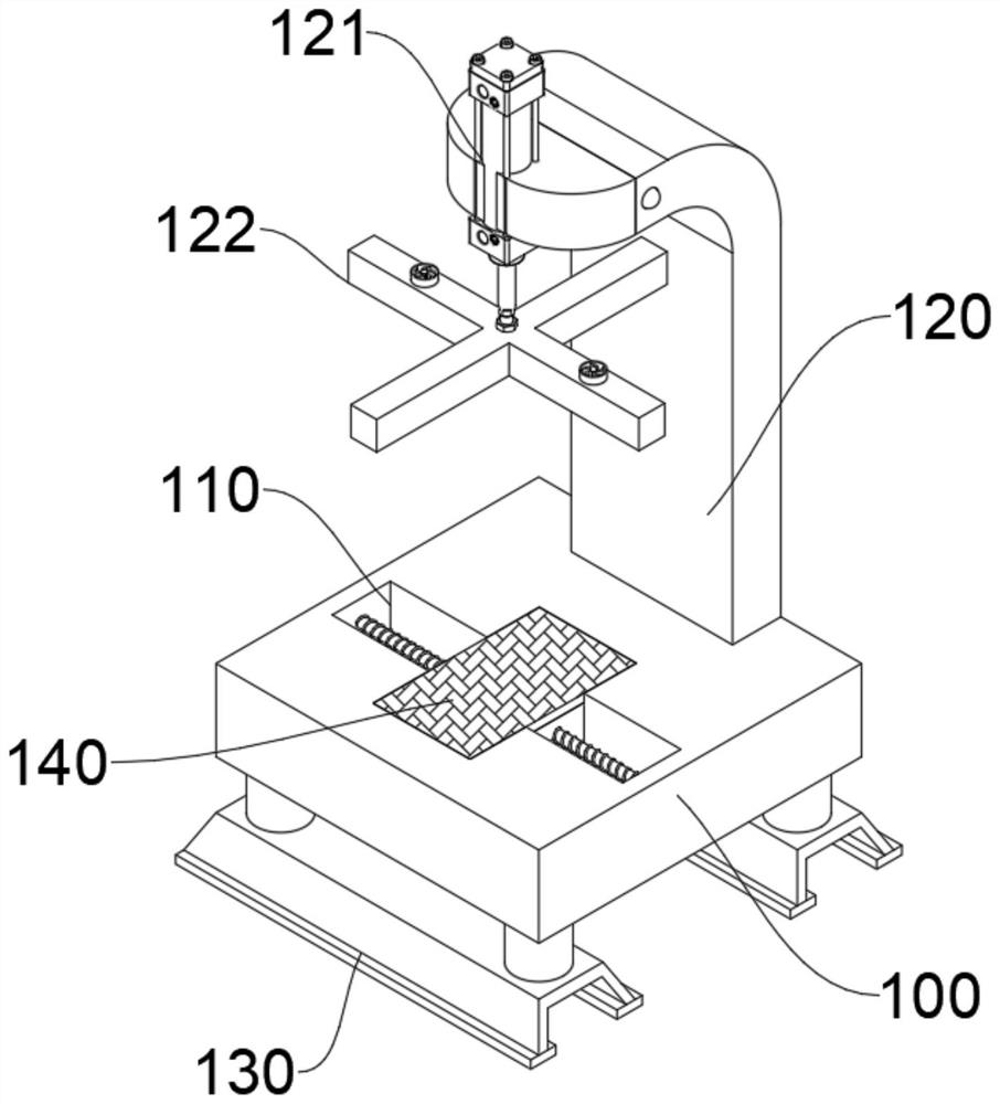
[0039] Base plate 100, base plate 100 top edge is provided with support plate 120, and support plate 120 is " L " shape, and support plate 120 end is provided with cylinder 121, and cylinder 121 piston rod end is connected with extruding plate 122, connects cylinder 121 Turn on the power to make it work, and the piston rod of the cylinder 121 slides up and down, which can drive the extrusion plate 122 to move up and down, so as to facilitate the subsequent extrusion of the spring stainless steel wire for strength and elasticity detection. It is a device or device that can sense the pressure signal and convert the pressure signal into an available output electrical signal according to certain rules. It can receive the elastic force brought by the compression of the spring stainless steel wire and ju...

Embodiment 2

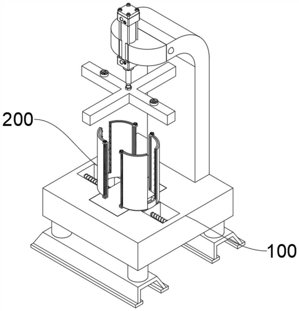
[0044] In order to adjust the limit range according to the size of the spring stainless steel wire, to ensure that the periphery of the spring stainless steel wire is limited by the limit arc plate 210, the difference between this embodiment and embodiment 1 is that please refer to Figure 5 shown, where:

[0045] There are two symmetrical moving slots 110 on the top of the bottom plate 100, the pressure sensor 140 is located between the two moving slots 110, the moving screw 111 rotates inside the moving slot 110, the bottom of the limit arc plate 210 is provided with a moving plate 220, the moving plate 220 is threadedly connected with the outer wall of the moving screw rod 111, so that the two moving screw rods 111 can be rotated simultaneously, so that the surface of the moving plate 220 at the bottom of the two limiting arc plates 210 slides along the screw thread on the outer wall of the moving screw rod 111, driving two The limit arc plate 210 gathers inward or spreads ...

Embodiment 3

[0048] In order to prevent the adjustment plate 231 from rotating with the adjustment screw 2121 and make the movable arc plate 230 slide up and down more stably, the difference between this embodiment and Embodiment 1 is that please refer to Image 6 shown, where:

[0049] The side wall of the adjustment plate 231 is provided with a positioning block 232, and the inner wall of the lifting plate 212 is provided with a positioning groove 2123. The positioning block 232 is compatible with the inside of the positioning groove 2123. When the outer wall of the adjustment screw 2121 slides up and down, the positioning block 232 is driven to slide inside the positioning groove 2123, and the direction in which the adjustment plate 231 slides can be limited to prevent the adjustment plate 231 from rotating with the adjustment screw 2121, so that the movable arc plate 230 moves up and down. Slide is more stable.


PUM


Abstract

The invention relates to the technical field of stainless steel wires, in particular to stainless steel wire strength detection equipment based on an elastic testing mechanism. The equipment at least comprises a bottom plate and two spring limiting mechanisms, wherein the top edge of the bottom plate is provided with a supporting plate, the end of the supporting plate is provided with a cylinder, the end of a cylinder piston rod is connected with an extrusion plate, and the top center of the bottom plate is provided with a pressure sensor; and the two spring limiting mechanisms are symmetrically arranged, each spring limiting mechanisms comprise limiting arc plates, open grooves are formed in the surfaces of the limiting arc plates, the ends of extrusion plates slide in the open grooves, lifting plates are arranged at the two ends of the limiting arc plates, adjusting lead screws are rotationally arranged in the lifting plates, two symmetrical movable arc plates slide on the outer sides of the limiting arc plates, adjusting plates are arranged at the ends, which are close to the bottom, of the movable arc plates, and the surfaces of the two adjusting plates are in threaded fit connection with the outer walls of the two adjusting lead screws correspondingly. The limiting range can be adjusted according to the size and height of the stainless steel wire of a spring, so that the detection stability is facilitated, and the detection accuracy is improved.

Description

technical field [0001] The invention relates to the technical field of stainless steel wires, in particular to stainless steel wire strength detection equipment based on an elastic testing mechanism. Background technique [0002] Stainless steel wire is one of the four types of stainless steel plates, tubes, shapes, and wires. It is a reprocessed product made of hot-rolled wire rods by cold drawing. Among them, stainless steel wires are produced into spring stainless steel wires, which have high strength and low cost. , has a long service life and is widely used in production, but the strength of spring stainless steel wire needs to be tested during production to test the elasticity of spring stainless steel wire to ensure that it can be used under a certain range of strength without damage. At present, testing equipment needs to be used when using The spring stainless steel wire is limited to avoid the impact of the spring dumping on the detection effect, but the current de...

Claims


Application Information

Patent Timeline
Patent Type & Authority Applications(China)
IPC IPC(8): G01N3/12G01N3/02
CPCG01N3/12G01N3/02
Inventor 李宝华单传宝孙连勤
Owner 安徽珂洁日用品有限公司
Learn More