High-efficiency photoelectric mounting bracket

A mounting bracket, high-efficiency technology, applied in the direction of machine/bracket, supporting machine, thin plate connection, etc., can solve the problems of inability to effectively guarantee the protection of the photoelectric switch, the installation is not firm, the contact area is small, and the friction coefficient is large. The effect of reducing workload and improving detection quality

Pending Publication Date: 2021-10-15
马金华
View PDF0 Cites 0 Cited by
  • Summary
  • Abstract
  • Description
  • Claims
  • Application Information

AI Technical Summary

Problems solved by technology

[0004] The main purpose of the present invention is to provide a high-efficiency photoelectric mounting bracket, which can effectively solve the problem that the traditional photoelectric bracket in the background technology is composed of two parts, a photoelectric bracket and a photoelectric bracket protective shell. , the direct contact area between the two is small, resulting in looseness between the brackets, which cannot effectively guarantee the protection function of the photoelectric switch. The bracket shell will be secured by bolts during installation, but as time goes by, the bolts will loosen, and When installing the photoelectric switch, the installation is not firm, and the problem that multiple groups of photoelectric switches cannot be installed

Method used


Image

  • High-efficiency photoelectric mounting bracket
  • High-efficiency photoelectric mounting bracket
  • High-efficiency photoelectric mounting bracket

Examples


Embodiment Construction

[0028] In order to make the technical means, creative features, goals and effects achieved by the present invention easy to understand, the present invention will be further described below in conjunction with specific embodiments.

[0029] In the description of the present invention, it should be noted that the terms "upper", "lower", "inner", "outer", "front end", "rear end", "both ends", "one end", "another end" The orientation or positional relationship indicated by etc. is based on the orientation or positional relationship shown in the drawings, and is only for the convenience of describing the present invention and simplifying the description, rather than indicating or implying that the referred device or element must have a specific orientation, use a specific Azimuth configuration and operation, therefore, should not be construed as limiting the invention. In addition, the terms "first" and "second" are used for descriptive purposes only, and should not be understood ...


PUM


Abstract

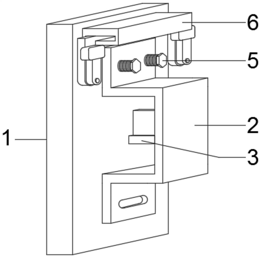
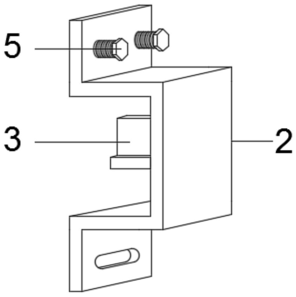
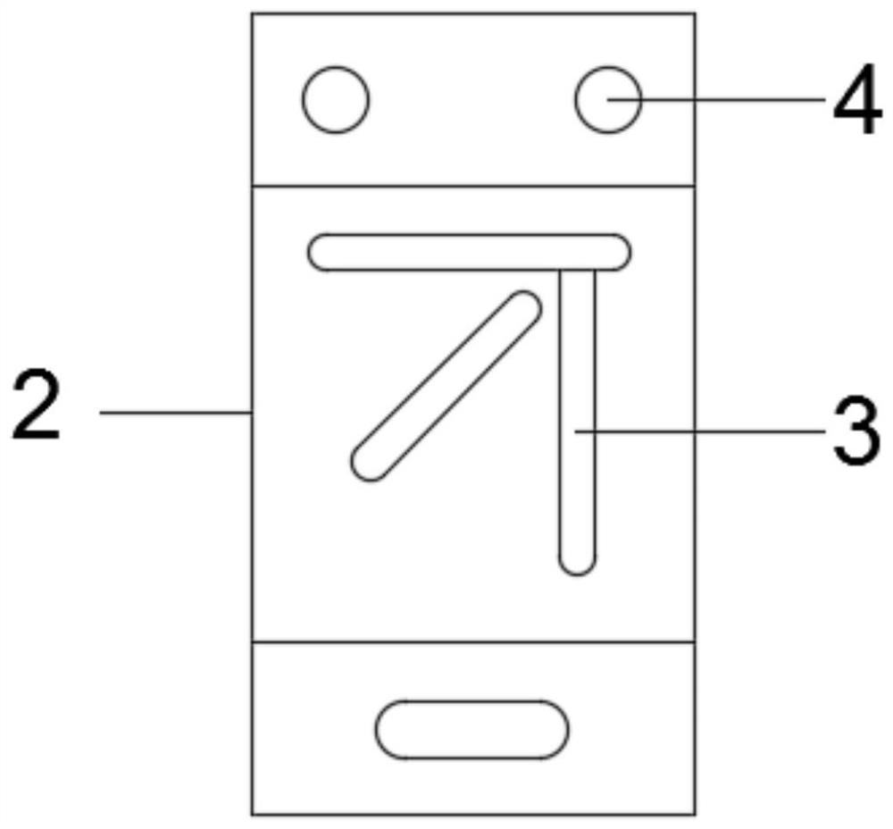
The invention discloses a high-efficiency photoelectric mounting bracket, and relates to the technical field of photoelectric switch brackets. The high-efficiency photoelectric mounting bracket comprises a mounting plate, a bracket shell and a photoelectric bracket, the bracket shell and the photoelectric bracket are mounted on the mounting plate, the bracket shell and the photoelectric bracket are of an integrated structure, the photoelectric bracket is Chinese character 'cai'-shaped, a screw hole is formed in the front end surface of the bracket shell, the interior of the screw hole is in threaded connection with a hexagon bolt, a fixing and locking mechanism is arranged on the front end face of the mounting plate, a clamping mechanism is arranged in the photoelectric bracket, the fixing and locking mechanism comprises a fixing block, a lifting plate, a rotating plate, a pressing block, a telescopic column and a rigid spring, and the clamping mechanism comprises a mounting frame, a lead screw, a bearing, a moving rod, a connecting rod and a clamp. The photoelectric mounting bracket is high in efficiency and convenient and fast to transport and mount, the loosening situation caused by long time is effectively avoided, the using effect is prevented from being affected by loosening, two sets of photoelectric switches can be used at the same time through the two sets of clamps, the using efficiency of the photoelectric switches is improved, and the detection quality of the photoelectric switches is improved.

Description

technical field [0001] The invention relates to the technical field of photoelectric switch brackets, in particular to a photoelectric installation bracket with high efficiency. Background technique [0002] Photoelectric switch (photoelectric sensor) is the abbreviation of photoelectric proximity switch. It uses the blocking or reflection of the light beam by the detected object, and the synchronous circuit is connected to the circuit to detect the presence or absence of the object. Objects are not limited to metals, all objects that can reflect light (or block light) can be detected. The photoelectric switch converts the input current into a light signal on the transmitter and emits it, and the receiver detects the target object according to the intensity or presence of the received light. The common photoelectric switch smoke alarm in the security system is often used in the industry to count the number of movements of the mechanical arm. [0003] Currently on the marke...

Claims


Application Information

Patent Timeline
IPC IPC(8): F16M11/04F16M13/02F16B5/02F16B39/10
CPCF16M11/041F16M13/02F16B5/02F16B39/10
Inventor 马金华
Owner 马金华
Why Eureka
Try Eureka