Cable multi-head active pay-off rack

A pay-off frame, active technology, applied in the direction of conveying filamentous materials, thin material handling, transportation and packaging, etc., can solve the problems of damage to the pay-off frame, simple structure, inclined center of gravity of the pay-off frame, etc., to reduce the workload , Improving the efficiency of pay-off and the effect of improving the safety of pay-off

Inactive Publication Date: 2021-10-15
厦门峻百冶贸易有限公司
View PDF0 Cites 2 Cited by
  • Summary
  • Abstract
  • Description
  • Claims
  • Application Information

AI Technical Summary

Problems solved by technology

[0002] According to the usage, the cable pay-off stand is also called cable reel support, wire shaft reel stand, cable pay-off support, etc. It is mainly used for cable retraction and release operations. The current cable pay-off stand has simple structure and single function, which cannot be done well. It is suitable for cable pay-off racks with different diameters, and the lifting of the pay-off rack is mainly carried out manually, which is not only time-consuming and laborious, but if the rising speeds on both sides of the pay-off rack are different, it is easy to cause damage to the pay-off rack or even cause the center of gravity of the pay-off rack to tilt and fall , there is a greater security risk

Method used


Image

  • Cable multi-head active pay-off rack
  • Cable multi-head active pay-off rack
  • Cable multi-head active pay-off rack

Examples


Embodiment Construction

[0022] In order to make the purpose and advantages of the present invention clearer, the present invention will be described in detail below in conjunction with the examples. It should be understood that the following words are only used to describe a kind of cable multi-head active pay-off rack or several specific implementation modes of the present invention. Without strictly limiting the scope of protection specifically claimed by the present invention, as used herein, the terms up, down, and left and right are not limited to their strict geometric definitions, but include reasonable and inconsistent tolerances for machining or human error, as follows Explain in detail the specific features of this kind of cable multi-head active pay-off rack:

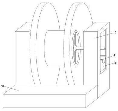
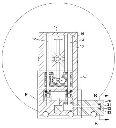
[0023] refer to Figure 1-8 , according to an embodiment of the present invention, a multi-head active pay-off rack for cables includes two main boxes 10, the main boxes 10 are arranged symmetrically on the left and right, and the f...


PUM


Abstract

The invention discloses a cable multi-head active pay-off rack. The cable multi-head active pay-off rack comprises two main box bodies, the main box bodies are arranged in a bilateral symmetry mode, synchronous transmission box bodies fixed to the front end surfaces of the main box bodies are arranged on the front sides of the main box bodies, lifting mechanisms are arranged in the main box bodies, clutch mechanisms are arranged on the lower sides of the lifting mechanisms, and a pay-off rotating mechanism is further arranged in the lifting mechanism on the left side. A cable reel is lifted by lifting seats which simultaneously ascend and descend on the two sides, the cable reel is prevented from toppling due to inclination of the gravity center, and meanwhile, the pay-off rack can be suitable for the cable reels with different diameters; the cable reel can be conveniently installed on a pay-off reel through a U-shaped center shaft clamping cavity, and the pay-off efficiency is improved; meanwhile, manual pay-off is replaced by the pay-off rotating mechanism, so that the work amount of a worker is greatly reduced; meanwhile, the pay-off rack has a self-locking function, so that the cable reel can stop rotating when the pay-off rack is suddenly powered off, and the pay-off safety is improved.

Description

technical field [0001] The invention relates to the related technical field of cable pay-off racks, in particular to an active multi-head cable pay-off rack. Background technique [0002] According to the usage, the cable pay-off stand is also called cable reel support, wire shaft reel stand, cable pay-off support, etc. It is mainly used for cable retraction and release operations. The current cable pay-off stand has a simple structure and a single function, which cannot be done well. It is suitable for cable pay-off racks with different diameters, and the lifting of the pay-off rack is mainly carried out manually, which is not only time-consuming and laborious, but if the rising speeds on both sides of the pay-off rack are different, it is easy to cause damage to the pay-off rack or even cause the center of gravity of the pay-off rack to tilt and fall. , there is a greater security risk. Contents of the invention [0003] The object of the present invention is to provide...

Claims


Application Information

Patent Timeline
Patent Type & Authority Applications(China)
IPC IPC(8): B65H49/32B65H67/02B65H49/34B65H63/00
CPCB65H49/325B65H67/02B65H49/34B65H63/00B65H2701/34
Inventor 符若兰
Owner 厦门峻百冶贸易有限公司
Why Eureka
Try Eureka