Gravity center adjusting mechanism for workpiece transfer machine shared by multiple vehicle types
A technology for adjusting the center of gravity and moving the loader, which is applied in the direction of manufacturing tools, metal processing equipment, auxiliary devices, etc., can solve the problems of poor stability and high maintenance costs, and achieve the goals of improving stability, reducing maintenance costs, and reducing maintenance costs Effect
- Summary
- Abstract
- Description
- Claims
- Application Information
AI Technical Summary
Problems solved by technology
Method used
Image

Examples
Embodiment 1
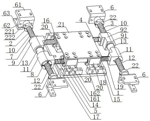
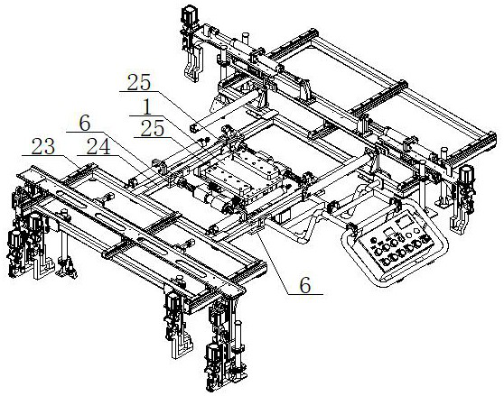
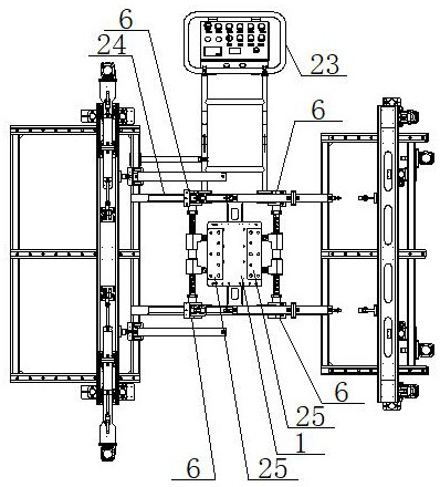
[0044] see Figure 1 to Figure 4 , a center-of-gravity adjustment mechanism for a workpiece transfer machine shared by multiple vehicle models, comprising a lifting seat 1 and an optical axis, the optical axis including a No. 1 optical axis 2, a No. 2 optical axis 3, a No. 3 optical axis 4, and a No. 4 optical axis 5. The No. 1 optical axis 2 and the No. 2 optical axis 3 are symmetrically arranged on both sides of the lifting base 1. Both ends of the No. 1 optical axis 2 and the No. 2 optical axis 3 are connected with mounting brackets 6, and the mounting brackets 6 is connected to the overall frame 24 of the transfer machine 23, the outer walls of the first optical axis 2 and the second optical axis 3 are fitted with a first bushing 7 and a second bushing 8, and the first bushing 7 A No. 1 mounting seat 9 is set on the outer wall of the No. 1 bushing 7 and a No. 1 compression spring 10 is set between the No. 1 bushing 7 and the mounting bracket 6. A No. 2 mounting seat 11 is ...
Embodiment 2
[0046] Basic content is the same as embodiment 1, the difference is:
[0047] The No. 1 bushing 7, the No. 2 bushing 8, the No. 3 bushing 14, and the No. 4 bushing 15 are all graphite bushings; the No. 1 bushing 7, the No. 2 bushing 8, and the No. 3 bushing 14 1, No. 4 bushing 15 are all T-shaped structures, No. 1 bushing 7, No. 2 bushing 8, No. 3 bushing 14, and No. 4 bushing 15 all include the bushing body and the flanges connected to the ends The bushing bodies of the No. 1 bushing 7 and the No. 2 bushing 8 are set on the outer walls of the No. 1 optical axis 2 and the No. 2 optical axis 3, and the No. 1 mounting seat 9 is set on the No. 1 bushing 7 On the outer wall of the bushing body, one end face of the flange of the No. 1 bushing 7 is connected to the end face of the No. 1 mounting seat 9, and the other end face of the flange of the No. 1 bushing 7 is connected to the No. 1 compression spring 10. fit; the No. 2 mounting seat 11 is set on the outer wall of the bushing ...
Embodiment 3
[0049] Basic content is the same as embodiment 1, the difference is:
[0050] The bottom surface of the lifting seat 1 is located at the positions outside the No. 3 mounting seat 16 and the No. 4 mounting seat 18. Limiting blocks 20 are installed; the center of gravity adjustment mechanism also includes a fixed plate 21, which is installed with the No. The top surface of the seat 16 and the fourth mounting seat 18 are connected; the center of gravity adjustment mechanism also includes a fixed seat 22, the fixed seat 22 is a T-shaped structure, and the fixed seat 22 includes a cylindrical section 221 and a disc 222, and the cylindrical The segment 221 is connected with the mounting bracket 6, the disc 222 is connected with the ends of the first optical axis 2 and the second optical axis 3, and the disc 222 is attached to the first compression spring 10 and the second compression spring 12 combine.
PUM
 Abstract
Description
Claims
Application Information
 - R&D
- Intellectual Property
- Life Sciences
- Materials
- Tech Scout
- Unparalleled Data Quality
- Higher Quality Content
- 60% Fewer Hallucinations
Browse by: Latest US Patents, China's latest patents, Technical Efficacy Thesaurus, Application Domain, Technology Topic, Popular Technical Reports.
© 2025 PatSnap. All rights reserved.Legal|Privacy policy|Modern Slavery Act Transparency Statement|Sitemap|About US| Contact US: help@patsnap.com