
Power capacitor clamping tool for power installation engineering

A technology for installation engineering and power capacitors, which is applied in the direction of capacitors, electrical components, springs/shock absorbers, etc., can solve the problems of power capacitor damage, loud noise, etc., and achieve the effect of avoiding damage and wide installation range

Inactive Publication Date: 2021-10-08
张芹
View PDF3 Cites 0 Cited by
  • Summary
  • Abstract
  • Description
  • Claims
  • Application Information

AI Technical Summary

Problems solved by technology

[0005] The purpose of the present invention is to solve the problems in the prior art that the installation of power capacitors has certain limitations and is easy to cause damage to power capacitors and generate relatively large noises, and proposes a power capacitor clamping tool for power installation engineering

Method used


Image

  • Power capacitor clamping tool for power installation engineering
  • Power capacitor clamping tool for power installation engineering
  • Power capacitor clamping tool for power installation engineering

Examples


Embodiment Construction

[0025] The following will clearly and completely describe the technical solutions in the embodiments of the present invention with reference to the accompanying drawings in the embodiments of the present invention. Obviously, the described embodiments are only some, not all, embodiments of the present invention.

[0026] In describing the present invention, it should be understood that the terms "upper", "lower", "front", "rear", "left", "right", "top", "bottom", "inner", " The orientation or positional relationship indicated by "outside", etc. is based on the orientation or positional relationship shown in the drawings, and is only for the convenience of describing the present invention and simplifying the description, rather than indicating or implying that the referred device or element must have a specific orientation, so as to Specific orientation configurations and operations, therefore, are not to be construed as limitations on the invention.

[0027] refer to Figure ...


PUM


Abstract

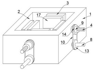
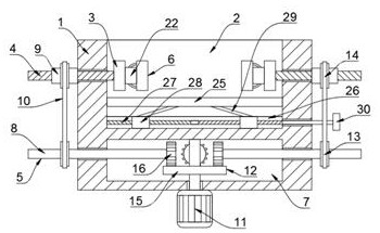
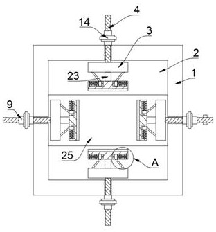
A power capacitor clamping tool for power installation engineering disclosed by the invention comprises a fixing mechanism, wherein the fixing mechanism comprises a bottom plate, a mounting groove is formed in the upper end of the bottom plate, the mounting groove is internally provided with four clamping plates, the opposite side walls of the four clamping plates are fixedly connected with threaded rods, the four threaded rods slidably penetrate through the bottom plate, a driving mechanism for driving the four threaded rods is arranged in the bottom plate, and damping mechanisms for damping the capacitor are arranged on the four clamping plates. By adopting the power capacitor clamping tool, noise generated by vibration when the power capacitor works can be reduced, the power capacitor cannot be locked, and the installation range of the power capacitor is wide.

Description

technical field [0001] The invention relates to the technical field of fixed tooling, in particular to a power capacitor clamping tool for power installation engineering. Background technique [0002] Power capacitors are capacitors used in power systems and electrical equipment. Any two metal conductors are separated by an insulating medium to form a capacitor. The capacitance of a capacitor is determined by its geometric size and the characteristics of the insulating medium between the two plates. When the capacitor is used under AC voltage, its reactive power is often used to represent the capacity of the capacitor. [0003] The power capacitor will vibrate during the working process. The existing clamping tool will lock the power capacitor when it is fixed. On the one hand, it is easy to cause damage to the power capacitor; Noise, moreover, the existing clamping tooling has a certain depth. When fixing the power capacitors of different punctures, it cannot ensure that t...

Claims


Application Information

Patent Timeline
Patent Type & Authority Applications(China)
IPC IPC(8): H01G2/04F16F15/067F16F15/02
CPCH01G2/04F16F15/067F16F15/02
Inventor 贾大鹏
Owner 张芹
Learn More