Eureka AIR delivers breakthrough ideas for toughest innovation challenges, trusted by R&D personnel around the world.

Upstream and downstream river channel trash grating cleaning mechanism for water conservancy project

A technology for water conservancy projects and cleaning mechanisms, which is applied in water conservancy projects, cleaning of open water surfaces, mechanical equipment, etc. It can solve problems such as manual disassembly, blockage, interception rows or interception nets that cannot be quickly adjusted in height, and achieve the effect of improving environmental protection

Inactive Publication Date: 2021-10-08
JIAXING JINXILAI TECH CO LTD
View PDF0 Cites 6 Cited by
  • Summary
  • Abstract
  • Description
  • Claims
  • Application Information

AI Technical Summary

Problems solved by technology

[0004] For these floating objects and aquatic plants, the main measure currently taken is to install garbage interception rows or interception nets on the river course. Using traditional interception rows or interception nets, after the garbage is intercepted, it can only be salvaged by ships, which is laborious and laborious. In turbulent rivers, the floating debris and aquatic plants that are constantly accumulated on the interception row or interception net cannot be discharged from the river in time, which may block the interception row or interception net and reduce the interception efficiency. On the other hand, the water level in the river will continue to increase. However, the traditional interception platoon or interception net cannot quickly adjust the height, and needs to be manually disassembled and reinstalled, which has certain defects

Method used


Image

  • Upstream and downstream river channel trash grating cleaning mechanism for water conservancy project
  • Upstream and downstream river channel trash grating cleaning mechanism for water conservancy project
  • Upstream and downstream river channel trash grating cleaning mechanism for water conservancy project

Examples


Embodiment Construction

[0032] The following will clearly and completely describe the technical solutions in the embodiments of the present invention with reference to the accompanying drawings in the embodiments of the present invention. Obviously, the described embodiments are only some, not all, embodiments of the present invention. Based on the embodiments of the present invention, all other embodiments obtained by persons of ordinary skill in the art without making creative efforts belong to the protection scope of the present invention.

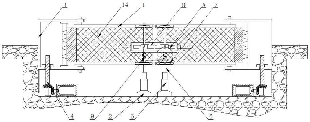
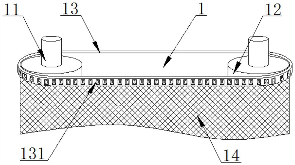
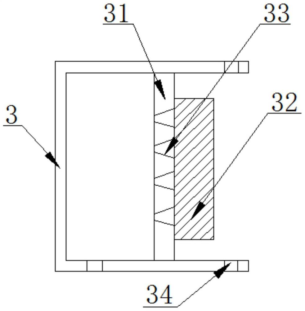
[0033] as attached figure 1 with attached Figure 10 The shown cleaning mechanism for upstream and downstream river channel trash grids for water conservancy projects includes a transmission device 1 and a transmission mechanism base 2. Both sides of the transmission device 1 are movably connected with a collection box 3, and the bottom surface of the inner cavity of the collection box 3 is A lifting mechanism 4 is movable and clamped, and a telescopic rod 5 ...


PUM


Abstract

The invention discloses an upstream and downstream river channel trash grating cleaning mechanism for a water conservancy project. The upstream and downstream river channel trash grating cleaning mechanism for the water conservancy project comprises a conveying device and a transmission mechanism base; collecting boxes are movably clamped to two sides of the conveying device; lifting mechanisms are movably clamped to the bottom faces of inner cavities of the collecting boxes; telescopic rods are fixedly installed on the top face of the transmission mechanism base; the top face of each telescopic rod is movably sleeved with a connecting rod; linkage gear mechanisms are fixedly installed at the top and the bottom of each connecting rod; and a water conservancy rotating box is movably clamped to the surface of the connecting rod. According to the scheme, the upstream and downstream riverway trash grating cleaning mechanism for the water conservancy project is provided with the conveying device, floating objects and aquatic plants flowing through the upstream and downstream of a riverway are intercepted through a filter screen, then a transmission belt is driven to rotate through rolling wheels, and meanwhile the filter screen is driven to rotate; and then the floating objects and the aquatic plants on the filter screen are scraped down through a scraping plate and are stored in the collecting boxes through one-way plates.

Description

technical field [0001] The invention relates to the technical field of water conservancy engineering, more specifically, the invention relates to a cleaning mechanism for upstream and downstream river channel trash grids used in water conservancy engineering. Background technique [0002] Water conservancy project is a general term for various engineering constructions built to control, utilize and protect surface and underground water resources and the environment. Also known as water engineering, water is an indispensable and precious resource for human production and life, but its natural state does not fully meet human needs. Only by building water conservancy projects can water flow be controlled, floods prevented, and water volume adjusted. Regulation and distribution to meet people's living and production needs for water resources. [0003] my country's rivers are seriously polluted. During heavy rain or flood season, a large number of floating objects and aquatic pl...

Claims


Application Information

Patent Timeline
Patent Type & Authority Applications(China)
IPC IPC(8): E02B15/06E02B15/10F03B11/08F03B13/00B01D29/03B01D29/96B01D29/64
CPCE02B15/06E02B15/10E02B15/104F03B11/08F03B13/00B01D29/03B01D29/96B01D29/6469Y02E10/20
Inventor 蒋晓伟
Owner JIAXING JINXILAI TECH CO LTD
Why Eureka
Eureka Blog
Learn More