Melting and cooling device for metal casting

A cooling device and metal casting technology, applied in the field of metal casting melting and cooling devices, can solve the problems affecting the quality of metal castings and cannot be cooled, and achieve the effects of ensuring production and processing quality, uniform and effective cooling and cooling

Inactive Publication Date: 2021-10-08
扬州市华胜铸造有限公司
View PDF0 Cites 1 Cited by
  • Summary
  • Abstract
  • Description
  • Claims
  • Application Information

AI Technical Summary

Problems solved by technology

[0004] In view of the above situation, in order to overcome the defects of the prior art, the present invention provides a metal casting melting cooling device, which effectively solves the problem that the existing metal casting water cooling equipment in the above background technology cannot fully and uniformly cool the metal castings. , which leads to the problem that the stress on each side of the metal casting is different and affects the quality of the metal casting

Method used


Image

  • Melting and cooling device for metal casting
  • Melting and cooling device for metal casting
  • Melting and cooling device for metal casting

Examples


Embodiment 1

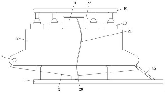
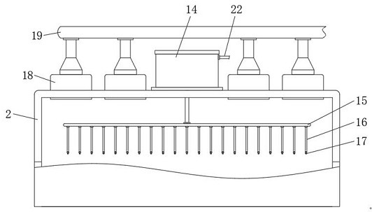
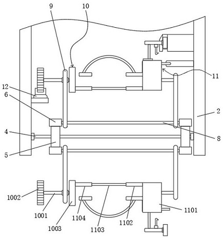
[0030] Embodiment one, by Figure 1 to Figure 6Given, the present invention includes a base 1, a cooling box 2 is installed on the top of the base 1, and a cooling water collection cover 3 is installed on the top of the cooling box 2. By setting the cooling water collection cover 3, water can be effectively collected and cooled. Rotating shaft 4 is mounted on the lower part of the inner side of box 2 to rotate equidistantly, first gear 5 is fixedly installed on both sides of rotating shaft 4, and transmission chain 6 is installed between the surfaces of first gear 5 on the same side of rotating shaft 4 A motor 7 is installed on one side of the surface of the cooling box 2, and the output end of the motor 7 is fixedly connected with one end of one of the rotating shafts 4, and through the setting of the rotating shaft 4, the first gear 5, the transmission chain 6 and the motor 7, it can effectively The two transmission chains 6 are equidistantly fixed with a fixed rod 8, and bo...

Embodiment 2

[0033] Embodiment two, on the basis of embodiment one, by Figure 5 Given, the middle part of the second disk 1101 side is provided with a sliding groove 13, the inside of the sliding groove 13 is equipped with an L-shaped pressing plate 23, the inner side of the L-shaped pressing plate 23 is fixedly installed with an arc bar 24, and one end of the arc bar 24 A square pressing plate 25 is fixedly installed, so as to clamp the placed metal casting.

Embodiment 3

[0034] Embodiment three, on the basis of embodiment two, by Figure 5 Provided, the inner side of the sliding groove 13 is provided with a sliding card slot 26, and the inside of the sliding card slot 26 is slidably equipped with a T-shaped slider 27, and one end of the L-shaped pressing plate 23 is fixedly connected with the T-shaped slider 27, and the T-shaped slider 27 A first spring 28 and a first corrugated protection ring 29 are installed between the bottom of the sliding card slot 26, and the first corrugated protection ring 29 is sleeved on the surface of the first spring 28, so that the L-shaped pressing plate 23 can be driven to move Reset adjustment.


PUM


Abstract

The invention relates to the technical field of metal processing equipment, discloses a melting and cooling device for metal casting, and solves the problem that the quality of a metal casting is affected due to different stresses on each surface of the metal casting due to the fact that conventional water-cooling cooling equipment for metal casting cannot comprehensively and uniformly cool the metal casting. The device comprises a base, a cooling box is mounted at the top of the base, a cooling water collecting cover is mounted at the top of the cooling box, rotating shafts are rotatably mounted between the lower portions of the inner side of the cooling box at equal intervals, first gears are fixedly mounted at two sides of each rotating shaft, and a transmission chain is mounted between the surfaces of the first gears at the same side of each rotating shaft. According to the melting and cooling device for metal casting, moving and rotating adjustment can be conducted on a metal casting part, and water spraying and cooling can be conducted on the metal casting part in the moving and rotating adjustment process so that it is guaranteed that each surface of the metal casting part can be uniformly and effectively cooled, and the production and processing quality of the metal casting part is also guaranteed.

Description

technical field [0001] The invention belongs to the technical field of metal processing equipment, in particular to a metal casting melting cooling device. Background technique [0002] Metal casting is to pour liquid metal into a mold cavity that is suitable for the shape and size of the part, and wait for it to cool and solidify to obtain blank parts; after casting, metal castings need to be cooled, and then stored or processed. One-step processing; the cooling of metal castings generally includes oil cooling, water cooling, room temperature cooling, lime sand cooling and furnace cooling. [0003] The existing metal casting water-cooled cooling equipment cannot fully cool the metal casting during use, so that the surface of the metal casting cannot be cooled uniformly, resulting in different stresses on each side of the metal casting and affecting the metal casting. The quality of the casting; therefore, for the current situation, it needs to be improved. Contents of th...

Claims


Application Information

Patent Timeline
Patent Type & Authority Applications(China)
IPC IPC(8): B22D30/00
CPCB22D30/00
Inventor 邵志芳
Owner 扬州市华胜铸造有限公司
Why Eureka
Try Eureka