A High Capacity Relay with Auxiliary Contact Isolation Mechanism
An isolation mechanism and auxiliary contact technology, applied in the direction of relays, electromagnetic relays, electromagnetic relay details, etc., can solve the problems of single auxiliary contact form, large auxiliary contact size, burning auxiliary contacts, etc., to avoid high and low loads The effects of connectivity, enhancing market competitiveness, and eliminating potential safety hazards
- Summary
- Abstract
- Description
- Claims
- Application Information
AI Technical Summary
Problems solved by technology
Method used
Image
Examples
Embodiment 1
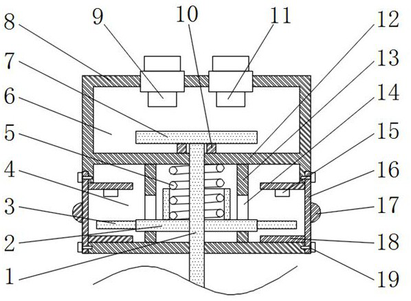
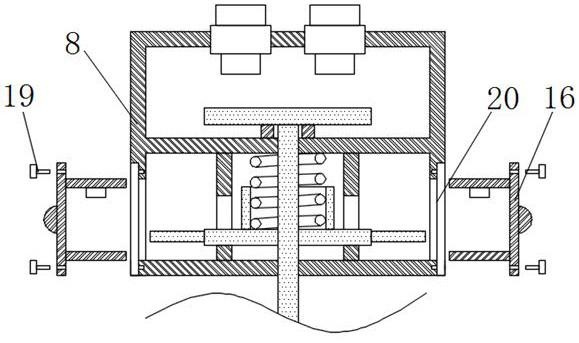
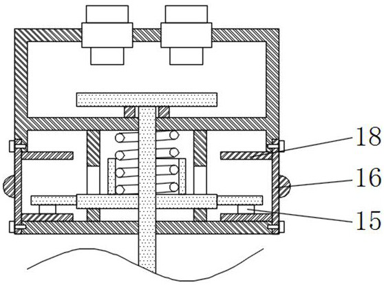
[0035] Such as figure 1 The shown high-capacity relay with auxiliary contact isolation mechanism includes a housing 8 with an incoming line static contact 9 and an outgoing line static contact 11 on the top and a sealing tube connected under the housing 8 (in the figure not shown), the housing 8 is provided with a moving contact 7 for touching the incoming line static contact 9 and the outgoing line static contact 11, and the lower end surface of the moving contact 7 is connected with a longitudinally extending and through Through the push rod 1 at the bottom of the housing 8, a moving iron core connected to the lower end of the push rod 1 is arranged in the sealing tube, and a coil (not shown in the figure) surrounds the moving iron core; the push rod 1 is fixedly sleeved with The insulating plate 2 located inside the housing 8, the first spring 5 sleeved on the push rod 1 is arranged between the insulating plate 2 and the insulating plate 12, and the middle part of the upper...
Embodiment 2
[0039] The difference between this embodiment and embodiment 1 is:
[0040] In this example, if Figure 4 As shown, the auxiliary static contact 15 is fixed on the inner side of the pull-out carrier 16, and one end of the auxiliary movable contact 3 is hinged to one of the mounting guide plates 18 toward the middle of the pull-out carrier 16 through a hinge shaft 23. On the end face, and the auxiliary static contact 15 is located on the trajectory of the auxiliary movable contact 3 rotating around the hinge shaft 23, the side of the auxiliary movable contact 3 facing away from the auxiliary static contact 15 is connected to the corresponding installation guide plate 18 The second spring 21 of the insulating plate 2 facing the auxiliary static contact 15 is fixed with an extension plate 22 for resisting the auxiliary movable contact 3 . If the hinged end of the auxiliary movable contact 3 is connected to the installation guide plate 18 below, the extension plate 22 can be driv...
Embodiment 3
[0043] The difference between this embodiment and embodiment 1 is:
[0044] In this example, if Figure 5As shown, the auxiliary static contact 15 is fixed on the inner surface of the drawing carrier 16, and the auxiliary movable contact 3 is longitudinally slidably connected between two installation guide plates 18, and the two installation guide plates 18 are both A slide rail 24 for horizontal sliding of the auxiliary movable contact 3 is fixed, a third spring 26 is connected between the auxiliary movable contact 3 and the pull-out carrier 16, and the side of the auxiliary movable contact 3 facing the insulating plate 2 An inclined block 25 is fixed, and the side of the inclined block 25 facing the insulating plate 2 is an inclined surface, and the side of the insulating plate 2 facing the auxiliary movable contact 3 is fixed with an extension plate 22 for resisting the inclined surface of the inclined block 25 . If the width of the inclined block 25 gradually increases fr...
PUM
 Abstract
Description
Claims
Application Information
 - Generate Ideas
- Intellectual Property
- Life Sciences
- Materials
- Tech Scout
- Unparalleled Data Quality
- Higher Quality Content
- 60% Fewer Hallucinations
Browse by: Latest US Patents, China's latest patents, Technical Efficacy Thesaurus, Application Domain, Technology Topic, Popular Technical Reports.
© 2025 PatSnap. All rights reserved.Legal|Privacy policy|Modern Slavery Act Transparency Statement|Sitemap|About US| Contact US: help@patsnap.com


