High-capacity relay with auxiliary contact isolation mechanism

An isolation mechanism and auxiliary contact technology, applied in the direction of relays, electromagnetic relays, electromagnetic relay details, etc., can solve the problems of single auxiliary contact form, large auxiliary contact size, burning auxiliary contacts, etc., to avoid high and low loads The effects of connectivity, enhancing market competitiveness, and eliminating potential safety hazards

Active Publication Date: 2021-10-01
中汇瑞德电子(芜湖)有限公司
View PDF6 Cites 0 Cited by
  • Summary
  • Abstract
  • Description
  • Claims
  • Application Information

AI Technical Summary

Problems solved by technology

[0003] The traditional relay mainly adds a set of auxiliary contacts on the top of the ceramic cavity to realize the monitoring of the main contacts. The effect is poor. When the main contact breaks the load, the arc easily jumps to the auxiliary contact, causing high and low loads to connect, and even burns the auxiliary contact. The reliability of the relay cannot be guaranteed; the auxiliary contact form of this structure is single, only the normally open structure, and it is difficult to meet the requirements of the relay for the normally closed auxiliary contact; One set is set on the top. When multiple sets of auxiliary contacts need to be set, the relay structure will increase in size and complex structure; in addition, there is no effective isolation between the auxiliary contacts and the main contacts of traditional relays. When the main contacts are burnt by arcing , metal particles and other spatters may splash on the auxiliary contacts, which will cause the auxiliary contacts to fail, thereby affecting the reliability of the relay, which is not conducive to improving the market competitiveness of the product
[0004] At present, in the prior art, a high-capacity relay with an auxiliary contact isolation mechanism is disclosed in the patent application publication number CN 112331525 A. Although this solution can solve the above-mentioned problems, it mainly realizes the main relay through the isolator. The isolation of contacts and auxiliary contacts has a complex structure, which is not convenient for the production and assembly of relays; and there is a large through hole in the middle of the isolator, which makes the isolation effect between the main contacts and auxiliary contacts insufficient

Method used


Image

  • High-capacity relay with auxiliary contact isolation mechanism
  • High-capacity relay with auxiliary contact isolation mechanism
  • High-capacity relay with auxiliary contact isolation mechanism

Examples


Embodiment 1

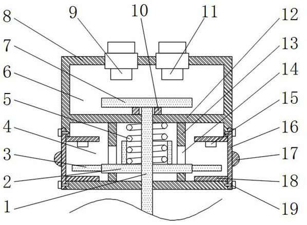
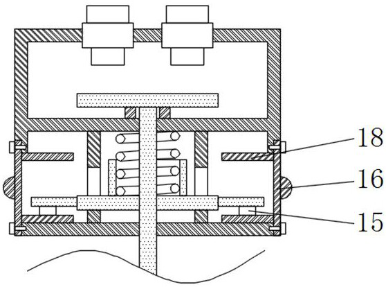
[0035] Such as figure 1 The shown high-capacity relay with auxiliary contact isolation mechanism includes a housing 8 with an incoming line static contact 9 and an outgoing line static contact 11 on the top and a sealing tube connected under the housing 8 (in the figure not shown), the housing 8 is provided with a moving contact 7 for touching the incoming line static contact 9 and the outgoing line static contact 11, and the lower end surface of the moving contact 7 is connected with a longitudinally extending and through Through the push rod 1 at the bottom of the housing 8, a moving iron core connected to the lower end of the push rod 1 is arranged in the sealing tube, and a coil (not shown in the figure) surrounds the moving iron core; the push rod 1 is fixedly sleeved with The insulating plate 2 located inside the housing 8, the first spring 5 sleeved on the push rod 1 is arranged between the insulating plate 2 and the insulating plate 12, and the middle part of the upper...

Embodiment 2

[0039] The difference between this embodiment and embodiment 1 is:

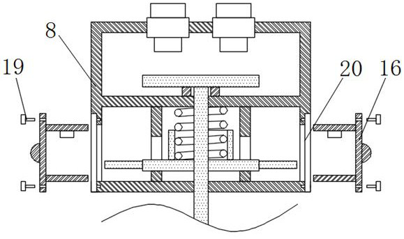
[0040] In this example, if Figure 4 As shown, the auxiliary static contact 15 is fixed on the inner side of the pull-out carrier 16, and one end of the auxiliary movable contact 3 is hinged to one of the mounting guide plates 18 toward the middle of the pull-out carrier 16 through a hinge shaft 23. On the end face, and the auxiliary static contact 15 is located on the trajectory of the auxiliary movable contact 3 rotating around the hinge shaft 23, the side of the auxiliary movable contact 3 facing away from the auxiliary static contact 15 is connected to the corresponding installation guide plate 18 The second spring 21 of the insulating plate 2 facing the auxiliary static contact 15 is fixed with an extension plate 22 for resisting the auxiliary movable contact 3 . If the hinged end of the auxiliary movable contact 3 is connected to the installation guide plate 18 below, the extension plate 22 can be driv...

Embodiment 3

[0043] The difference between this embodiment and embodiment 1 is:

[0044] In this example, if Figure 5As shown, the auxiliary static contact 15 is fixed on the inner surface of the drawing carrier 16, and the auxiliary movable contact 3 is longitudinally slidably connected between two installation guide plates 18, and the two installation guide plates 18 are both A slide rail 24 for horizontal sliding of the auxiliary movable contact 3 is fixed, and a third spring 26 is connected between the auxiliary movable contact 3 and the bracket of the pull-out carrier 16, and the auxiliary movable contact 3 faces one side of the insulating plate 2 An inclined block 25 is fixed, and the side of the inclined block 25 facing the insulating plate 2 is an inclined surface, and the side of the insulating plate 2 facing the auxiliary movable contact 3 is fixed with an extension plate 22 for resisting the inclined surface of the inclined block 25 . If the width of the inclined block 25 grad...


PUM


Abstract

The invention discloses a high-capacity relay with an auxiliary contact isolation mechanism, and belongs to the technical field of relays. Thehigh-capacity relay with an auxiliary contact isolation mechanismcomprises a shell, a push rod and an insulating plate, wherein the interior of the shell is divided into an upper containing cavity and a lower containing cavity through an isolation plate, a main contact is located in the upper containing cavity, an auxiliary contact is arranged in the lower containing cavity, the shell on the peripheral side of the lower containing cavity is provided with a detachable pull-out carrier plate, the upper end and the lower end of the pull-out carrier plate are fixedly provided with symmetrically-arranged installation guide plates, the installation guide plates are horizontally arranged, the auxiliary contact comprises an auxiliary movable contact and an auxiliary static contact, the auxiliary static contact is fixedly connected with the installation guide plate or the pull-out carrier plate, and the auxiliary movable contact is in transmission connection with the insulating plate. According to the invention, the main contact and the auxiliary contact can be effectively isolated, the requirements of the relay on the normally-open auxiliary contact and the normally-closed auxiliary contact can be met, the requirement of arranging a plurality of groups of auxiliary contacts can be met, the structure is simple, the relay is convenient to produce and assemble, and the isolation effect between the main contact and the auxiliary contact is relatively good.

Description

technical field [0001] The invention relates to the technical field of relays, in particular to a high-capacity relay with an auxiliary contact isolation mechanism. Background technique [0002] The relay is an electric control device that causes the controlled quantity to undergo a predetermined step change in the electrical output circuit when the change of the input quantity (excitation quantity) meets the specified requirements. circuit) and the controlled system (also known as the output circuit), which plays the role of automatic adjustment, safety protection and conversion circuit in the circuit. With the rise of green energy, high-capacity relays are widely used in high-voltage DC loads such as vehicles, photovoltaics, and charging piles. In view of the above-mentioned application scenarios of high-voltage DC loads, it is often necessary to set up auxiliary contacts to monitor the status of the main contacts and perform low-voltage Linkage control to improve the saf...

Claims


Application Information

Patent Timeline
IPC IPC(8): H01H50/54H01H50/02
CPCH01H50/54H01H50/541H01H50/02
Inventor 杜展
Owner 中汇瑞德电子(芜湖)有限公司
Why Eureka
Try Eureka