
Three-dimensional wind field efficient simulation method based on delay effect

A simulation method and wind field technology, applied in special data processing applications, instruments, geometric CAD, etc., can solve the problems of increasing the number of simulation process variables, reducing calculation efficiency, and increasing the dimension of cross-spectral density matrix, etc., to achieve strong operation high efficiency, improved decomposition efficiency, and simple method

Active Publication Date: 2021-10-01
DALIAN UNIV OF TECH
View PDF7 Cites 1 Cited by
  • Summary
  • Abstract
  • Description
  • Claims
  • Application Information

AI Technical Summary

Problems solved by technology

However, with more and more large-scale structures, the number of variables in the simulation process will increase accordingly, and the dimension of the cross-spectral density matrix will increase. It will become more difficult to perform Cholesky decomposition on it, resulting in a greatly reduced computational efficiency.
Some scholars consider introducing the "Taylor Freeze Hypothesis" into the wind field simulation to replace the longitudinal spatial correlation of the wind field, and make a phase offset for the fluctuation of each frequency point. This method will increase the final superposition and summation. workload

Method used


Image

  • Three-dimensional wind field efficient simulation method based on delay effect
  • Three-dimensional wind field efficient simulation method based on delay effect
  • Three-dimensional wind field efficient simulation method based on delay effect

Examples


Embodiment Construction

[0023] In order to make the purpose, features and advantages of the present invention more obvious and understandable, the technical solutions in the embodiments of the present invention will be clearly and completely described below in conjunction with the accompanying drawings in the embodiments of the present invention. Obviously, the following The described embodiments are only some, not all, embodiments of the present invention. Based on the embodiments of the present invention, all other embodiments obtained by persons of ordinary skill in the art without making creative efforts belong to the protection scope of the present invention.

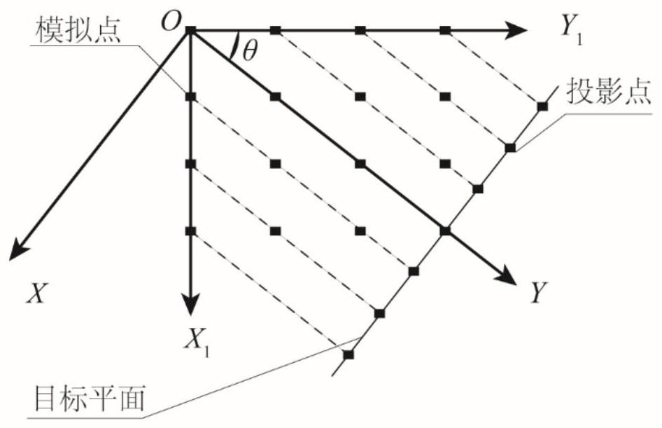
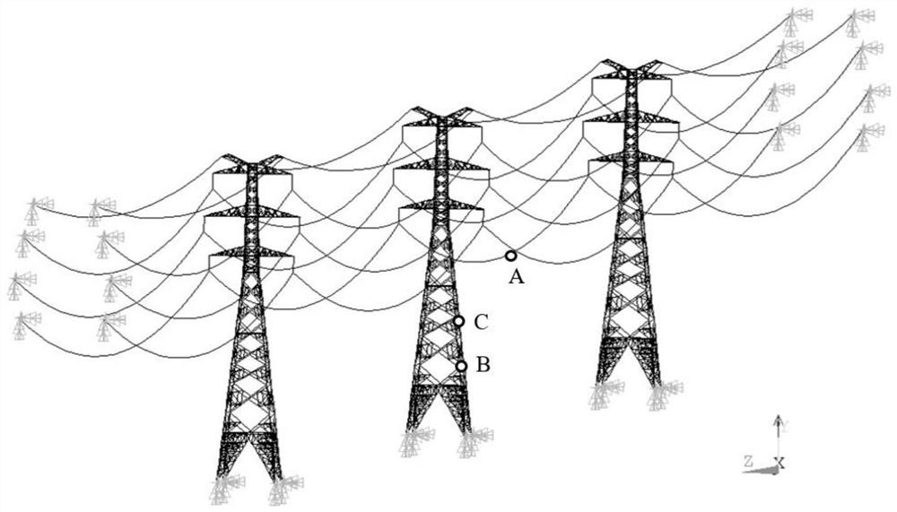
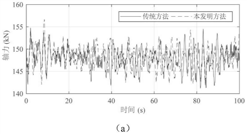
[0024] see Figure 1 to Figure 3 , the embodiment of the present invention proposes an efficient three-dimensional wind field simulation method by taking the transmission tower-line system as an example.

[0025] Implementation case data source: see "FuXand L H N, Dynamic analysis of transmission tower-line system subjected to wind and r...


PUM


Abstract

The invention discloses a three-dimensional wind field efficient simulation method based on a delay effect, and belongs to the technical field of structural wind engineering. The method for generating the wind speed time history mainly comprises the steps of determining coordinates and an initial coordinate system of simulation points according to a structural drawing, transforming the coordinate system to enable a Y axis to be parallel to the wind speed direction, obtaining a three-dimensional model of N structural simulation points, projecting all the simulation points of the three-dimensional model to a target two-dimensional plane, converting the simulation points into projection points in a two-dimensional plane, calculating wind speed delay time, namely required time from each point to the projection points on the target plane, adopting a two-dimensional coherence function to consider spatial correlation of different simulation points in the transverse direction and the vertical direction, generating fluctuating wind speed by using a harmonic superposition method, and obtaining wind speed time histories of all the points by using the delay time. The statistical characteristics of the data obtained by the time delay method are similar to the result of the traditional three-dimensional method, but the simulation efficiency is greatly improved; and meanwhile, the method is simple to operate and has a reasonable theoretical background.

Description

technical field [0001] The invention belongs to the technical field of structural wind engineering, in particular to a numerical simulation method for generating wind speed time histories. Background technique [0002] Wind disaster is one of the natural disasters that cause the greatest loss of personnel and property. For large structures, wind load is an important design load, and even plays a decisive role. The existing wind resistance design mainly adopts the methods of wind tunnel test, numerical simulation and field measurement. Numerical simulation is an important supplement to the test. The method is convenient and repeatable, and it can be used for wind load verification and design calculation. [0003] Wind loads imposed on structures require artificial synthesis of wind speed time histories with specific spectral density and spatial correlation as excitations. In engineering, natural wind is usually approximately regarded as a smooth Gaussian process with various...

Claims


Application Information

Patent Timeline
IPC IPC(8): G06F30/17G06F30/23G06F113/06G06F119/02
CPCG06F30/17G06F30/23G06F2113/06G06F2119/02
Inventor 付兴张兴恒李宏男
Owner DALIAN UNIV OF TECH
Learn More