A Power Calculation Method of Ball Screw Type Energy Feed Shock Absorber
A ball screw type, power calculation technology, applied in calculation, computer-aided design, instruments, etc., can solve the problems of complex system structure, high processing order, and slow simulation analysis speed, so as to improve modeling efficiency and facilitate Driving control, easy-to-adjust effects
- Summary
- Abstract
- Description
- Claims
- Application Information
AI Technical Summary
Problems solved by technology
Method used
Image
Examples
Embodiment 1
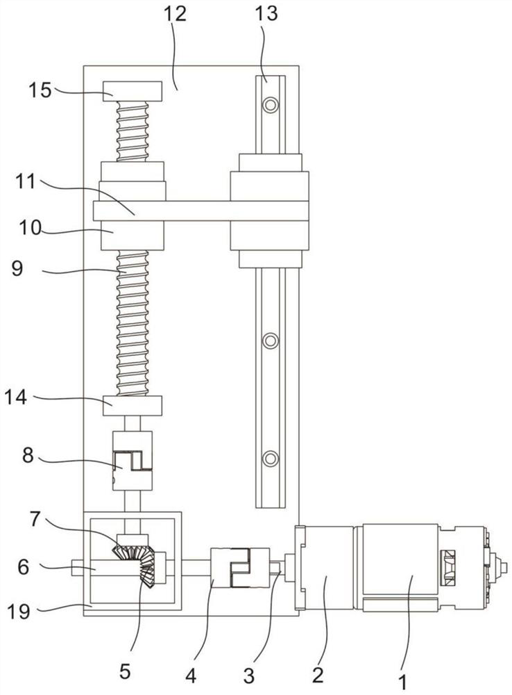
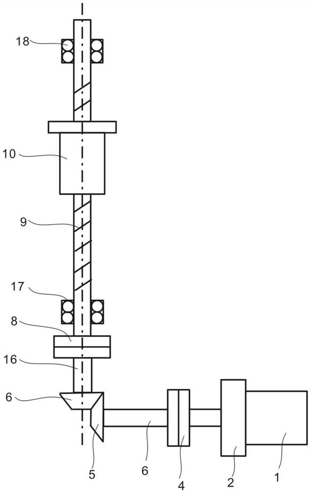
[0054] refer to figure 1 , is the first embodiment of the present invention, this embodiment provides a kind of ball screw type energy-feeding shock absorber, and it comprises fixed plate 12, is connected with drive shaft 9 rotatably on the fixed plate 12, and fixed plate 12 The upper part is fixedly connected with the first supporting seat 15 and the second supporting seat 14 arranged at intervals in the height direction. The second bearing 17 is rotatably connected to the second support base 14, the transmission shaft 9 is threaded with a moving nut 10 that can slide up and down along the fixed plate 12, and the fixed plate 12 is fixed with a sliding guide rail 13. A lifting plate 11 is fixedly connected to the nut 10, and the lifting plate 11 is slidably connected to the sliding guide rail 13. The fixed plate 12 below the transmission shaft 9 is fixedly connected to the gear box 2, and the outer end of the gear box 2 is fixedly connected to There is an energy-feeding motor...
Embodiment 2
[0057] As the second embodiment of the present invention, this embodiment provides a power calculation method of a ball screw type energy-feed shock absorber, using this invention to verify that the shock absorber has vibration damping performance, which can be achieved by loading different drives The force simulates the output power of the feeder motor 1 under different working conditions.
[0058] (S1) Convert the 3D model into Adams for multi-rigid body modeling of the virtual prototype, define material properties, add constraints, load the drive according to the derived driving force formula, obtain the system model, and obtain model parameters;
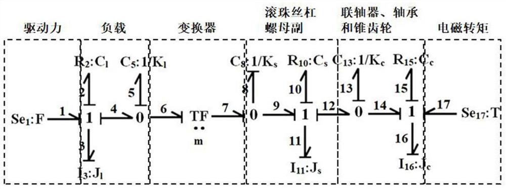
[0059] (S2) extracting key components in the three-dimensional model, establishing a physical model of the shock absorber, and establishing a power bond diagram model according to the physical model of the shock absorber;
[0060] (S3) deduce the state equation of the power bond graph model according to the power bond graph model...
Embodiment 3
[0088] It is the third embodiment of the present invention. The difference between this embodiment and Embodiment 1 and Embodiment 2 is that the simulation is performed for a specific virtual prototype, and the simulation parameters of the virtual prototype are shown in Table 1.
[0089] Table 1 Simulation parameters of virtual prototype
[0090]
[0091] When performing virtual prototype multi-rigid body modeling, the settings are as follows:
[0092] Fixed displacement amplitude is 50mm
[0093] MOTION=step(time,0,0,0.5,50)+step(time,0.5,0,1,-50)
[0094] Driving force acting on the nut:
[0095] SFORCE1=0.075*0.046*WM(.shockabsorber.rotor.cm) / 10.5*44*2*pi / 5*sin(2*pi*1*time)
[0096] Since the electromagnetic torque acts as a resistance torque and is opposite to the direction of the driving force, the driving force makes the nut move up and down, so the direction of the electromagnetic torque changes accordingly:
[0097] Electromagnetic torque direction 1:
[0098] ...
PUM
 Abstract
Description
Claims
Application Information
 - R&D
- Intellectual Property
- Life Sciences
- Materials
- Tech Scout
- Unparalleled Data Quality
- Higher Quality Content
- 60% Fewer Hallucinations
Browse by: Latest US Patents, China's latest patents, Technical Efficacy Thesaurus, Application Domain, Technology Topic, Popular Technical Reports.
© 2025 PatSnap. All rights reserved.Legal|Privacy policy|Modern Slavery Act Transparency Statement|Sitemap|About US| Contact US: help@patsnap.com


