
Torque vector distribution system, vehicle and torque vector distribution method

A distribution system and torque vectoring technology, applied in vehicle components, non-deflectable wheel steering, steering mechanism, etc., can solve the problems of heavy and complex torque vector distribution differential, energy consumption, high cost, etc., to facilitate unmanned driving. Controls, tight structures, space-saving effects

Pending Publication Date: 2022-02-11
肖多娇
View PDF1 Cites 0 Cited by
  • Summary
  • Abstract
  • Description
  • Claims
  • Application Information

AI Technical Summary

Problems solved by technology

Its disadvantages are: the torque vectoring differential is very heavy and complicated, expensive to manufacture, and will cause additional energy consumption, and its application is limited to Audi S4, S5 and S6, BMW X5 M and X6 M, Lexus RCF and other models
The torque vectoring rear axle control system launched by ZF can be used in four-wheel drive and rear-wheel drive vehicles. It is mainly distributed by torque vectoring on the left and right wheels. The ZF torque vectoring control unit on the BMW X5 mainly includes a planetary gear set , multi-plate wet brakes, and drive control devices, etc., because of the high cost, this kind of torque vectoring is currently only used in luxury cars

Method used


Image

  • Torque vector distribution system, vehicle and torque vector distribution method
  • Torque vector distribution system, vehicle and torque vector distribution method
  • Torque vector distribution system, vehicle and torque vector distribution method

Examples


Embodiment 1

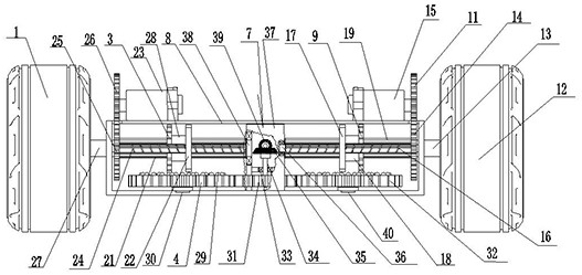
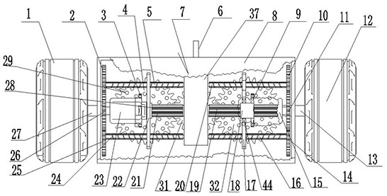
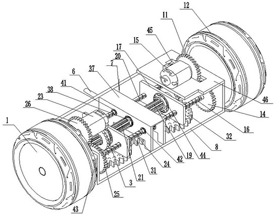
[0041] Embodiment 1: A torque vectoring distribution system, which is provided with a driving part, on both sides of the driving part, a first bead tooth engagement device 4 and a second bead tooth engagement device 32 are connected through power transmission, on the first bead tooth engagement device 4 The first bead meshing wheel 3 is provided, and the first bead meshing wheel 3 is connected with the first torque output shaft 27 in a power transmission that can slide along the torque output shaft. The first toggling part 22 is connected, and the first toggling part 22 drives the first bead gear 3 to engage and separate the bead rings 29 of different diameters on the first bead gear 4 for power transmission. The second bead gear 32 is provided with a second bead gear 9, and the second bead gear 9 is connected to the second torque output shaft 13 in a power transmission that can slide along the torque output shaft. The second bead gear 9 It is connected with the second toggle ...

Embodiment 2

[0042] Embodiment 2: A kind of torque vector distribution system is provided with a driving part, and the driving part is composed of a driving gear 31, a deceleration part 7 for power transmission with the driving gear 31, and a power input part 6 for power transmission with the deceleration part 7, The power input part 6 is connected with the fuel-burning engine. Both sides of the driving gear 31 are connected with the first bead gear 4 and the second bead gear 32 through power transmission, the first bead gear 4 is provided with the first bead meshing wheel 3, and the first bead gear The wheel 3 and the first torque output shaft 27 are connected in a power transmission that can slide along the torque output shaft, and the first pinion meshing wheel 3 is connected with the first toggle part 22 that can slide along the torque output shaft, and the first toggle Part 22 drives the first bead gear 3 and the bead ring 29 of different diameters on the first bead gear 4 to engage a...

Embodiment 3

[0043] Embodiment 3: A torque vectoring distribution system is provided with a driving part, and the driving part is composed of a driving gear 31, a deceleration part 7 for power transmission with the driving gear 31, and a power input part 6 for power transmission with the deceleration part 7. Speed ​​reduction part 7 is made up of reduction box 37, is located in reduction box 37 and the drive bevel gear 39 that carries out power connection with power input part 6, and the transmission bevel gear 35 that meshes with drive bevel gear 39 and drive gear 31 carries out power transmission is formed, power The input part 6 is connected with the new energy motor. Both sides of the driving part are connected with the first bead gear 4 and the second bead gear 32 through power transmission. The first bead gear 4 is provided with the first bead gear 3, and 3 is connected with the first torque output shaft 27 for power transmission that can slide along the torque output shaft, and the ...


PUM


Abstract

The invention discloses a torque vector distribution system, a vehicle thereof and a vehicle torque vector distribution method, and relates to a torque vector distribution technology, a torque vector distribution device and a corresponding vehicle. The system is characterized in that: a first bead tooth meshing device and a second bead tooth meshing device are connected to the two sides of a driving part, bead tooth meshing wheels are arranged on the bead tooth meshing devices respectively, the bead tooth meshing wheels are in power transmission connection with the torque output shaft in the mode that the bead tooth meshing wheels can slide along the torque output shaft, the two bead tooth meshing wheels are connected with a first shifting part and a second shifting part which can slide along the torque output shaft, and the shifting parts drive the bead tooth meshing wheels to be meshed with and separated from bead tooth rings with different diameters on the bead tooth meshing devices in a power transmission manner, so that the rotating speed, the steering direction and the static state of a wheel mounted on the torque output shaft are controlled. The system is simple and compact, more than 50% of parts can be reduced, and the space can be saved; gear shifting and clutching are completed through one component, and control convenience and reliability are improved; each wheel can be independently controlled, and the obstacle crossing performance is excellent; reverse torque can be distributed to the wheels on the two sides, so that the vehicle can smoothly turn or turn around when encountering a sharp turn or a narrow field; unmanned driving control is facilitated; and the production cost can be obviously reduced.

Description

technical field [0001] The present invention relates to torque vector distribution technology, device and corresponding vehicle. Background technique [0002] Handling is one of the important criteria for evaluating whether a car drives well. When the traditional technology vehicle is turning, the wheels on both sides are due to the relationship of centrifugal force, so that the vertical load of the wheels on both sides is transferred, and the vertical load of the wheel on the inner side of the bend is smaller than that of the outer wheel, resulting in a change in the friction between the wheel and the ground. When cornering, although the friction circle of the inner wheel becomes smaller, the traditional technology uses the method of splitting the torque equally, which results in excessive torque of the inner wheel and insufficient torque of the outer wheel, resulting in slippage and rollover Situation happens. With the improvement of people's demand for vehicle handling ...

Claims


Application Information

Patent Timeline
Patent Type & Authority Applications(China)
IPC IPC(8): B60K17/04B60K17/08B60K17/02B62D11/04
CPCB60K17/043B60K17/08B60K17/02B62D11/04
Inventor 肖多娇
Owner 肖多娇
Learn More