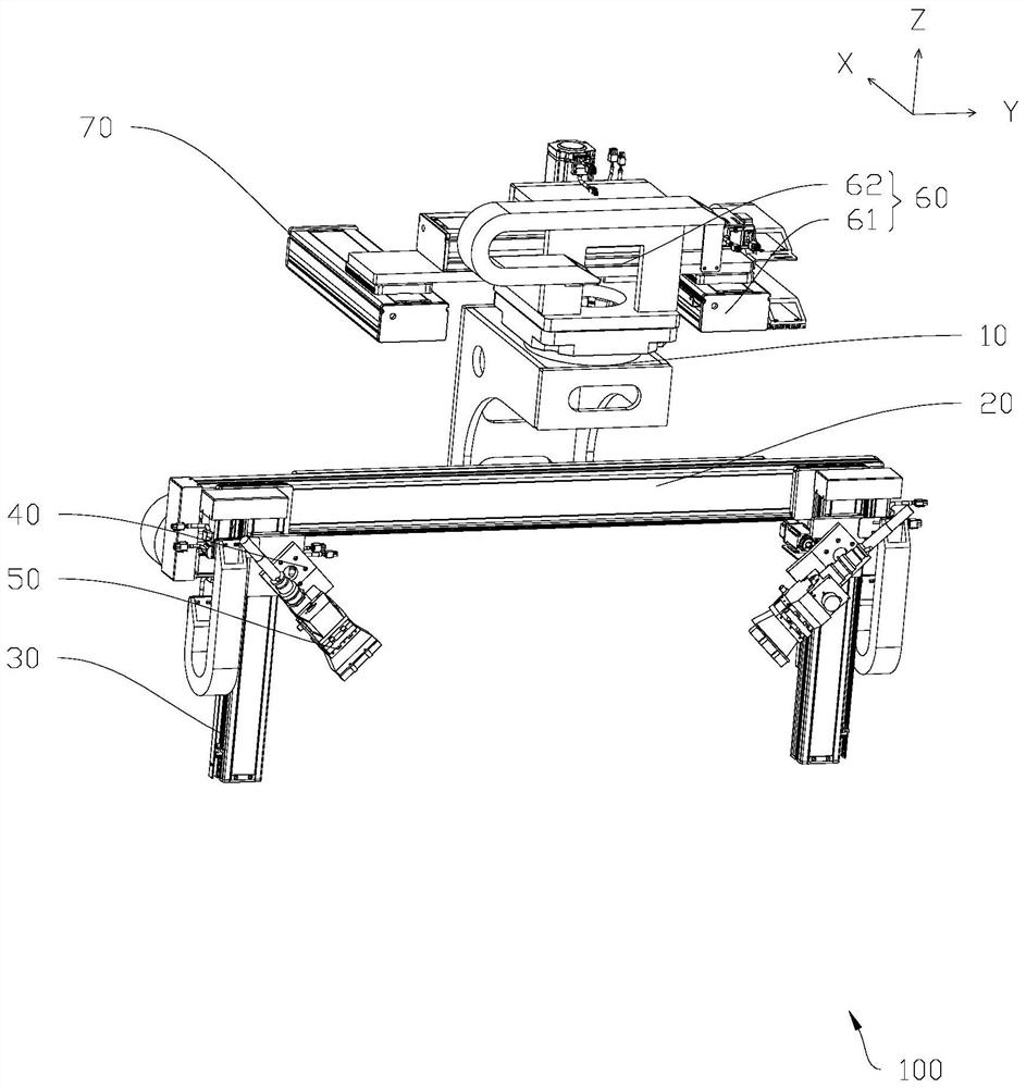
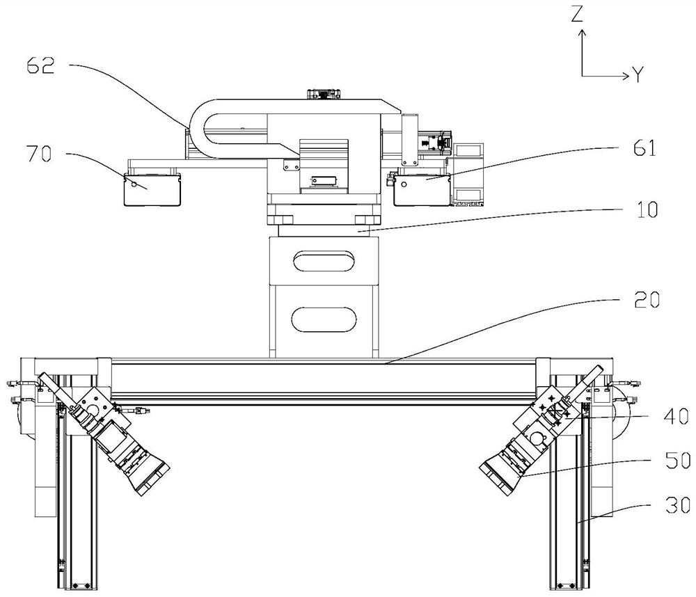
An axis-controlled motion control structure
A technology of motion control and axial transmission mechanism, applied in the direction of program control, digital control, comprehensive factory control, etc., can solve the problems of difficult to meet the diversified product structure, increase the difficulty of running cost programming, and achieve compact structure and economical design. effect of space
- Summary
- Abstract
- Description
- Claims
- Application Information
AI Technical Summary
Problems solved by technology
Method used
Image
Examples
no. 1 approach
[0040] like Figure 4 As shown, when the cleaning surface of the product to be cleaned is an annular arc-shaped surface, the first axial transmission mechanism 61 and the second axial transmission mechanism 62 are controlled so that the center of the first rotary table 10 is The axis coincides with the center of the product, adjust the height of the laser 50 relative to the vertical beam 30, rotate the second rotary table 40 so that the laser beam is facing the surface to be cleaned, and the first rotary table 10 rotates The scanning path that drives the laser beam is the belt cleaning surface.
no. 2 approach
[0042] like Figure 5-6 As shown, when the cleaning surface of the product to be cleaned is the inner wall surface and the inner bottom surface, the first axial transmission mechanism 61 and the second axial transmission mechanism 62 are controlled to make the central axis of the first rotary table 10 Coinciding with the center position of the product, by adjusting the second rotary table 40 to make the laser 50 face vertically downward and facing the inner bottom surface, the first rotary table 10 rotates to drive the laser beam to complete the cleaning and then turn the second component toward the inner bottom surface. The central axis moves in the direction of the rotation to reduce the rotation radius, and then the first rotary table 10 rotates until the entire inner bottom surface is cleaned.
[0043] When the width of the inner wall of the cleaning surface of the product to be cleaned is relatively large, by controlling the second rotary table 40 to rotate the laser 50 i...
no. 3 approach
[0045] like Figure 7-8 As shown, when the cleaning surface of the product to be cleaned is the inner wall surface, and the width of the inner wall surface of the cleaning surface of the product to be cleaned is relatively small, the second rotary table 40 is controlled to make the laser 50 move toward the direction close to the central axis Rotation, that is to form a cross-shaped scanning form, to avoid the situation where the two second components are too close to interfere with each other, the first rotary table 10 can be rotated 180 degrees to complete one cycle of cleaning; The position of the vertical beam 30 is adjusted to adjust the vertical height of the laser beam until the cleaning of the inner wall surface of the full height is completed.
[0046] When the cleaning surface of the product to be cleaned is the outer peripheral surface, first adjust the position of the second component on the beam 20, and then control the second rotary table 40 so that the laser 50 i...
PUM
 Abstract
Description
Claims
Application Information
 - R&D
- Intellectual Property
- Life Sciences
- Materials
- Tech Scout
- Unparalleled Data Quality
- Higher Quality Content
- 60% Fewer Hallucinations
Browse by: Latest US Patents, China's latest patents, Technical Efficacy Thesaurus, Application Domain, Technology Topic, Popular Technical Reports.
© 2025 PatSnap. All rights reserved.Legal|Privacy policy|Modern Slavery Act Transparency Statement|Sitemap|About US| Contact US: help@patsnap.com


