Optical lens and imaging equipment
A technology of optical lens and imaging surface, applied in the field of imaging lens, can solve the problems of small field of view, high lens cost, and large volume, and achieve the effect of low cost and good imaging performance
- Summary
- Abstract
- Description
- Claims
- Application Information
AI Technical Summary
Problems solved by technology
Method used
Image

Examples
no. 1 example
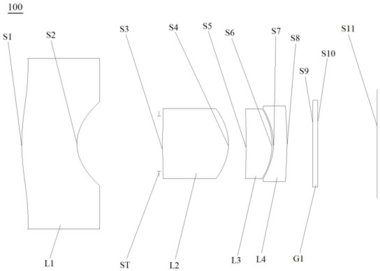
[0071] see figure 1 , which is a schematic structural view of the optical lens 100 provided in the first embodiment of the present invention, the optical lens 100 includes: a first lens L1, a stop ST, a second lens L2, The third lens L3, the fourth lens L4 and the filter G1.
[0072] Wherein, the first lens L1 has negative refractive power, the object side S1 of the first lens is convex, and the image side S2 of the first lens is concave.
[0073] The second lens L2 has positive refractive power, the object side S3 of the second lens is convex at the near optical axis, and the image side S4 of the second lens is convex.
[0074] The third lens L3 has positive refractive power, the object side S5 of the third lens is concave, and the image side S6 of the third lens is convex.
[0075] The fourth lens L4 has negative refractive power, the object side S7 of the fourth lens is concave, and the image side S8 of the fourth lens is convex at the near optical axis.
[0076] Wherein...
no. 2 example
[0088] see Image 6 , which is a schematic structural view of the optical lens 200 provided by the second embodiment of the present invention, the structure of the optical lens 200 provided by the second embodiment of the present invention is substantially the same as that of the optical lens 100 provided by the first embodiment, and the difference mainly lies in , the radius of curvature and material selection of each lens are different.
[0089] Please refer to Table 3, which shows the relevant parameters of each lens in the optical lens provided by the second embodiment of the present invention.
[0090] table 3
[0091]
[0092] Please refer to Table 4, which shows the surface coefficients of each aspheric surface of the optical lens provided by the second embodiment of the present invention.
[0093] Table 4
[0094]
[0095] Please refer to Figure 7 , Figure 8 , Figure 9 and Figure 10 , respectively show the astigmatism curve, vertical axis chromatic abe...
no. 3 example
[0100] see Figure 11 , which is a schematic structural view of the optical lens 300 provided by the third embodiment of the present invention, the structure of the optical lens 300 provided by the third embodiment of the present invention is substantially the same as that of the optical lens 100 provided by the first embodiment, and the difference mainly lies in , the radius of curvature and material selection of each lens are different.
[0101] Please refer to Table 5, which shows the relevant parameters of each lens in the optical lens provided by the third embodiment of the present invention.
[0102] table 5
[0103]
[0104] Please refer to Table 6, which shows the surface coefficients of each aspheric surface of the optical lens 100 provided by the third embodiment of the present invention.
[0105] Table 6
[0106]
[0107] Please refer to Figure 12 , Figure 13 , Figure 14 and Figure 15, which respectively show the astigmatism curve, vertical axis chr...
PUM
 Abstract
Description
Claims
Application Information
 - R&D
- Intellectual Property
- Life Sciences
- Materials
- Tech Scout
- Unparalleled Data Quality
- Higher Quality Content
- 60% Fewer Hallucinations
Browse by: Latest US Patents, China's latest patents, Technical Efficacy Thesaurus, Application Domain, Technology Topic, Popular Technical Reports.
© 2025 PatSnap. All rights reserved.Legal|Privacy policy|Modern Slavery Act Transparency Statement|Sitemap|About US| Contact US: help@patsnap.com