A tie-dyeing device for textile dyeing

A technology for textiles and mounting panels, which is applied in the field of tie-dyeing, and can solve problems such as dye corrosion, cloth easy to scatter, and operator's physical impact

Active Publication Date: 2021-11-12
海门市冬夏纺织品有限公司
View PDF0 Cites 0 Cited by
  • Summary
  • Abstract
  • Description
  • Claims
  • Application Information

AI Technical Summary

Problems solved by technology

A dyeing method in which the fabric is partially ligated during dyeing so that it cannot be dyed. It is one of the traditional Chinese hand-dyeing techniques. The tie-dyeing process is divided into two parts: tying and dyeing. The fabric is dyed after being tied, sewed, bound, embroidered, clipped, etc. However, most of the tie-dyeing methods are still tied on the table for dip-dyeing or partial dyeing. This method, on the one hand, It is easy to drip the dye on the table when it is partially drip-dyeed. At the same time, when the cloth is rotated and drip-dyeed, the cloth is also easy to scatter, which affects the tie-dyeing effect. In addition, most tie-dyeing needs to be done at the same time. Put the ligated cloth into the dye, and some dyes are corrosive to a certain extent. When the human hand is immersed in the dye, such operation for a long time will easily have a certain impact on the operator's body

Method used


Image

  • A tie-dyeing device for textile dyeing
  • A tie-dyeing device for textile dyeing
  • A tie-dyeing device for textile dyeing

Examples


Embodiment 1

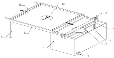
[0030] Such as Figure 1-8 As shown, a tie-dyeing device for textile dyeing provided by the present invention includes a dipping box 1 and an operating table 2, a drain pipe 3 is arranged on the lower wall of one side of the dipping box 1, and the bottom side wall of the operating table 2 is symmetrical. There are two supporting legs 4, and the dipping box 1 is also provided with a supporting bracket 5, the front end and the rear end wall of the supporting bracket 5 are respectively provided with connecting rods 6, and one end wall of the two connecting rods 6 is respectively provided with The first slider 7, the top wall of the dipping box 1 is also provided with an adjustment mechanism 8, the adjustment mechanism 8 includes the first screw rod 9, the mounting plate 10 and the adjustment block 11, and the wall at the middle position of the bottom of the console 2 is also provided with a rotating Mechanism 12, rotating mechanism 12 comprises fixed disc 13, rotating disc 14 and...

Embodiment 2

[0032] Such as Figure 6 , Figure 7 and Figure 8As shown in the adjusting mechanism of a tie-dyeing device for textile dyeing, the adjusting mechanism 8 is also provided with a first chute 20 in the front end and the rear end wall of the dipping box 1 respectively, and the top of the two first chute 20 has through holes. There are also first turning grooves 21 respectively provided in the inner wall body, and the adjustment mechanism 8 is also provided with two fixing plates 22 symmetrically on the wall body above the front end of the dipping tank 1, and the two fixing plates 22 are fixedly installed on the dipping dyeing tank 1 by welding. On the wall of the front end of the case 1, a block 23 is also provided on the wall above the rear end of the dipping case 1, and the block 23 is fixedly installed on the back wall of the dipping case 1 by welding, and the wall above the first screw rod 9 is provided with There is a first turning block 24, and the first turning block 24...

Embodiment 3

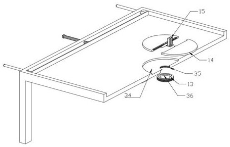
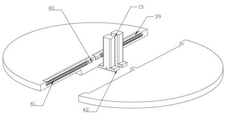
[0034] Such as figure 2 and image 3 As shown in the rotating mechanism of a tie-dyeing device for textile dyeing, the rotating mechanism 12 is also provided with a placement groove 34 in the bottom wall of the console 2, and the console 2 is also provided with a placement groove 34 in the wall at the bottom of the placement groove 34. Screw groove 35, fixed disc 13 is screwed into and installed in screw groove 35, also is fixedly installed with fixing groove 36 in the wall body in the middle position of block 23, and rotating disc 14 is interspersed in the fixing groove 36 by the plug-in block on the bottom wall body, fixed A second chute 39 is respectively provided in the front end and the rear end wall of the disk 13, and a first fixing rod 40 is respectively arranged in the two second chute 39, and the front end and the rear end wall of the first fixing rod 40 are welded respectively. fixedly installed on the wall at one end of the second chute 39, the outer walls of the...


PUM


Abstract

The invention discloses a tie-dyeing device for textile dyeing, which comprises a dipping box and an operating table. A drainage pipe is arranged on the lower wall of one side of the dipping box, and two symmetrically arranged on the side wall of the bottom of the operating table. Supporting legs, the dipping tank is also provided with a support bracket, the front end and the rear end wall of the support bracket are respectively provided with connecting rods, and the first slider is respectively provided on one end wall of the two connecting rods , The top wall of the dipping tank is also provided with an adjustment mechanism, the adjustment mechanism includes a first screw, a mounting plate and an adjustment block, and a rotation mechanism is also provided in the wall at the middle position of the bottom of the operation table. A tie-dyeing device for textile dyeing according to the present invention: through the setting of the rotating mechanism, the cloth can be easily clamped and rotated, and the cloth can be conveniently formed into common spiral folds. The arrangement of the limiting mechanism is convenient for temporarily limiting the rotated cloth to prevent it from falling apart and affecting the subsequent dripping.

Description

technical field [0001] The invention relates to the technical field of tie-dyeing, in particular to a tie-dyeing device for textile dyeing. Background technique [0002] Tie-dyeing, known in ancient times as zipping, twisting, clamping and dyeing, is a traditional and unique dyeing process of the Han nationality. A dyeing method in which the fabric is partially ligated during dyeing so that it cannot be dyed. It is one of the traditional Chinese hand-dyeing techniques. The tie-dyeing process is divided into two parts: tying and dyeing. The fabric is dyed after being tied, sewed, bound, embroidered, clipped, etc. However, most of the tie-dyeing methods are still tied on the table for dip-dyeing or partial dyeing. This method, on the one hand, It is easy to drip the dye on the table when it is partially drip-dyeed. At the same time, when the cloth is rotated and drip-dyeed, the cloth is also easy to scatter, which affects the tie-dyeing effect. In addition, most tie-dyeing ne...

Claims


Application Information

Patent Timeline
Patent Type & Authority Patents(China)
IPC IPC(8): D06B11/00D06B23/04D06B23/20
CPCD06B11/0056D06B23/04D06B23/20
Inventor 周夏燕
Owner 海门市冬夏纺织品有限公司
Why Eureka
Try Eureka